HyperMesh and BatchMesher

Constraints Panel

Constraints Panel

Previous topic Next topic Expand/collapse all hidden text  

Constraints Panel

Previous topic Next topic JavaScript is required for expanding text JavaScript is required for the print function  

Location:   Analysis page


Use the Constraints panel to place constraints or enforced displacements on a model. This is accomplished by assigning a degree of freedom (DOF) constraint to the node.

Constraints are load config 3 and are displayed with a triangle that connects to the node, with the dof numbers that apply to the node beside the triangle.


Panel Usage


The Constraints panel consists of separate subpanels for creating and editing constraints.

constraints_panel

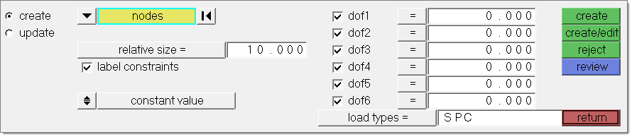
While both subpanels share many common inputs, the settings you specify are not shared between them, for example, you can change the value for each degree of freedom on the Edit subpanel without changing the values already specified for the same DOF's on the Create subpanel.


Subpanels and Inputs


The Constraints panel contains the following subpanels:

hmtoggle_arrow1Create

Panel Inputs

Input

Action

entity selector

Choose between nodes, comps, surfs, sets, points or lines.

In any case, the constraints are applied to nodes; this selection simply determines how those nodes are selected.  Geometric points select the nodes at which they exist. Comps select all of the nodes contained within the chosen component.

If you choose comps or sets, the constraints are drawn using a single indicator.

When nodes is selected, use the switch to change the selection mode.

nodes

Select individual nodes.

faces_edges_nodes

faces

Select all of the nodes on 2D and 3D faces.

If there are discontinuities on a 2D face, then only the nodes inbetween the discontinuities will be selected.

faces_edges_faces_nodes

2D faces ext

Select all of the nodes on a 2D face that contain discontinuities.

faces_edges_2d_face_ext_nodes

loops

Select all of the nodes on continuous free edges that make a closed loop simultaneously, such as the perimeter of a hole.

Only valid for SHELL elements.

faces_edges_loops_nodes

free edges

Select all of the nodes on free edges of elements.

If there are discontinuities on an edge, then only the nodes on the free edges inbetween the discontinuities will be selected.

Only valid for SHELL elements.

faces_edges_free_edges_nodes

free edges ext

Select all of the nodes on free edges of elements that contain discontinuities.

Only valid for SHELL elements.

faces_edges_free_edges_ext_nodes

edges

Select all of the nodes on free edges or shared edges (butt joints, L/corner joints, and T-joints) of elements.

If there are discontinuities on an edge, then only the nodes on the edge inbetween the discontinuities will be selected.

Only valid for SHELL elements.

faces_edges_edges_nodes

edges ext

Select all of the nodes on free edges or shared edges (butt joints, L/corner joints, and T-joints) of elements that contain discontinuities.

Only valid for SHELL elements.

faces_edges_edges_ext_nodes

display

Appears when comps or sets are selected. This button allows you to indicate where in the model you wish the indicator to be drawn.

relative size

Determines how large, in model units, constraints are  displayed relative to the model size.

label constraints

Check this box to have the constraints include text labels.

constant value / curve

Determine whether the constraint should be a constant value or use curve-based values. If curve, choose the desired curve.

face angle / individual selection

Face angle

Value used to determine which of the selected elements are to have constraints applied. For constraints applied to faces, once the starting face has been identified, the normals of the adjacent remaining faces are tested. If the angle between the normals is less than the face angle, a constraint is applied to the adjacent element. This process continues until all of the free faces have been tested. For a constraint applied to edges, the process is similar except that the angle between edges is used instead of the angle between faces.

Only available when the entity selector is set to nodes and the selection mode is set to faces, 2d faces ext, free edges, free edges ext, edges, or edges ext.

Individual Selection

Select individual elements on a face or select individual free/shared edges of elements.

Only available when the entity selector is set to nodes and the selection mode is set to faces, free edges, or edges.

edge angle

Splits edges that belong to a given face.

When the edge angle is 180 degrees, edges are the continuous boundaries of faces. For smaller values, these same boundary edges are split wherever the angle between segments exceeds the specified value. A segment is the edge of a single element.

Only available when the entity selector is set to nodes and the selection mode is set to free edges, free edges ext, edges, or edges ext.

xscale

Can be used instead of selecting a curve. Specify a scale factor for the curve’s X values.

dof1 - dof6

For each degree of freedom that you wish to constrain, click the checkbox that corresponds to it. Type in a value for the constraint.

load types

Click the button to reveal a list of available load types to choose from.  The available types depend on the current solver profile.


hmtoggle_arrow1Update

Panel Inputs

Input

Action

entity selector

Choose between nodes, surfs, comps, points or lines.

In any case, the constraints are applied to nodes; this selection simply determines how those nodes are selected.  Geometric points select the nodes at which they exist. Comps select all of the nodes contained within the chosen component.

If you choose comps or sets, the constraints are drawn using a single indicator.

display

Appears when comps or sets are selected. This button allows you to indicate where in the model you wish the indicator to be drawn.

relative size

Determines how large, in model units, constraints are  displayed relative to the model size.

label constraints

Check this box to have the constraints include text labels.

constant value / curve

Determine whether the constraint should be a constant value or use curve-based values. If curve, choose the desired curve.

xscale

Can be used instead of selecting a curve. Specify a scale factor for the curve’s X values.

dof1 - dof6

For each degree of freedom that you wish to constrain, click the checkbox that corresponds to it. Type in a value for the constraint.

load types

Click the button to reveal a list of available load types to choose from.  The available types depend on the current solver profile.


See Also:

HM-4040: Working with Loads on Geometry

Loads on Geometry

An Alphabetical List of HyperMesh Panels