|
»Click here to display Table of Contents«
|

Linear 1d Panel |

|

|

|

|
|
Linear 1d Panel |
|
|
|

|
|
»Click here to display Table of Contents«
|
Linear 1d Panel |
|
|
|
|
|
Linear 1d Panel |
|
|
|
|
Location: 1D page
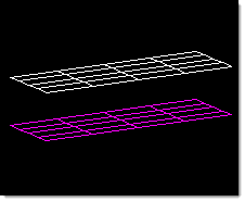
Use the Linear 1d panel to create one-dimensional elements.
Plot elements are 2-noded elements used for display purposes. Plot elements are element config 2 and are displayed as a line between two nodes. They have no properties.
One example of the use of plot elements is in a model where you have created a complex structure made up of two planes each containing a thousand elements. If, after creating your model, you determine that you would like to have 1000 gap elements between those two planes, you can create plot elements between all the nodes by using linear 1d. After the plot elements have been created, it is possible to change the plot elements to gap elements by changing the value of the configuration to that of gaps (by using the config edit panel). It is then possible to assign gap properties to those gap elements and to run the model. This eliminates having to create the gap elements individually.
There are no subpanels on the Linear 1d panel. All inputs and command buttons are located on the main panel.
Input |
Action |
||||
from: elems |
Indicate the elements where you want the plot elements to begin.
|
||||
from: alignment |
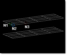
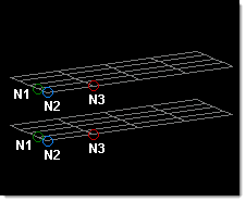
Optional: define the from line’s alignment:
|
||||
to: elems |
Indicate the elements where you want the plot elements to end by picking them on your model, or click elems again and choose from the extended entity selection menu.
|
||||
to: alignment |
Optional: define the to line’s alignment:
|
||||
density = |
Enter the number of plot elements you want created between each of the selected elements. |
||||
element config |
Choose the desired element configuration, if necessary. Available options depend on the current solver profile. |
The following action buttons appear:
Input |
Action |
create |
Creates new linear elements between the nodes of the selected elements. |
reject |
Undoes the most recent linear element creation. |
return |
Exits the panel. |
| • | Each group must contain an equal number of elements. |
| • | The alignment nodes (if used) must be placed in the same position and order on the first and second group of elements. |
| • | If you do not specify the from alignment or to alignment, the alignment will be determined automatically. |