Model Files
This exercise uses the propeller.hm file, which can be found in the hm.zip file. Copy the file(s) from this directory to your working directory.
Exercise: Translating Nodes to Increase the Length of a Propeller Blade
In this tutorial, you will increase the length of a propeller blade by 100 units, using freehand morphing.
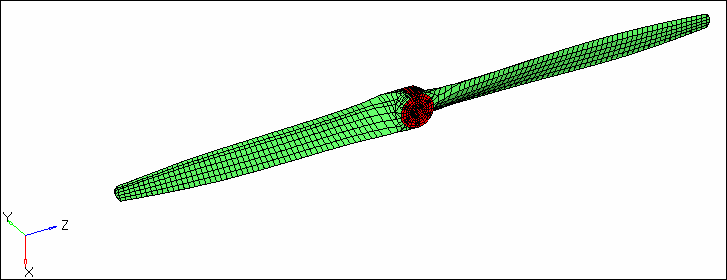
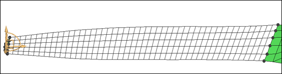
Figure 1: Original blade
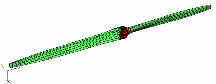
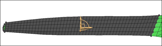
Figure 2: Blade after morphing
Step 1: Load the model.
| 1. | Start HyperMesh Desktop. |
| 2. | Open a model file by clicking File > Open > Model from the menu bar, or clicking  on the Standard toolbar. on the Standard toolbar. |
| 3. | In the Open Model dialog, open the propeller.hm file. A model appears in the graphics area. |
Step 2: Morph the blade.
Method 1: Fixed value based
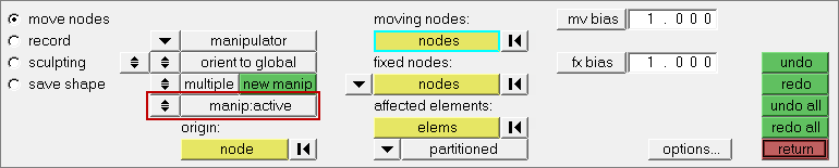
| 1. | Open the move nodes subpanel by clicking Morphing > Free Hand from the menu bar. |
| 2. | Set the morphing method to translate. |
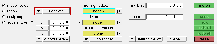
| 3. | In the z= field, enter -100. |
| 4. | In the Model browser, View folder, right-click on View1 and select Show from the context menu. |
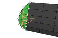
| 5. | Use the moving nodes and fixed nodes selectors to select the nodes indicated in the following image. |
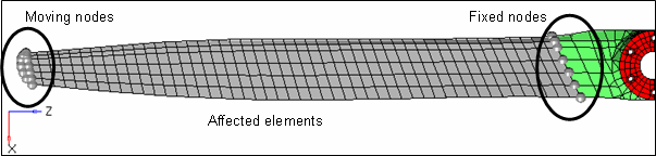
Figure 3: Node and element selections.
| 6. | Use the affected elements selector to select the elements between the fixed nodes and moving nodes. |
| 7. | In the mv bias and fx bias fields, keep the default values (1.00). |
| 8. | Click morph. HyperMesh alters the blade of the propeller. |
| Note: | The length of the propeller blade increased by 100. The fixed nodes did not move. HyperMesh stretched the affected elements evenly to maintain element quality. The stretching of the elements took place between the moving nodes and the fixed nodes. |
| 9. | Restore the propeller back to its original shape by clicking undo. |
Method 2: Interactive graphic manipulator base
| 10. | In the move nodes subpanel, set the morphing method to manipulator. |
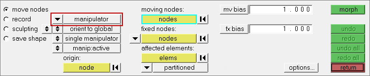
| 11. | Leave the other parameters and options set to their default values. |
| 12. | In the Model browser, View folder, right-click on View1 and select Show from the context menu. |
| 13. | Use the moving nodes and fixed nodes selectors to select the nodes indicated in the following image. |
Figure 3: Node and element selections.
| 14. | Use the affected elements selector to select the elements between the fixed nodes and moving nodes. A manipulator appears. |
| 15. | Optional: Move the manipulator to a different location by activating the origin: nodes selector and selecting another node as the origin. |
| 16. | Zoom in and rotate close the manipulator area. |
| 17. | Translate the nodes by clicking and dragging one of the three yellow arrows of the manipulator. |
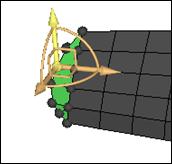
| 18. | Rotate the nodes about the center of the manipulator by clicking and dragging one of the three yellow arcs of the manipulator. |
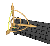
| 20. | Move the nodes in a plane by clicking and dragging one of the three yellow right angles of the manipulator. |
| 21. | Create more than one manipulator at a time by setting the single manipulator/multiple toggle to multiple. |
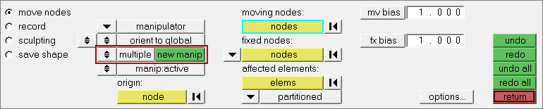
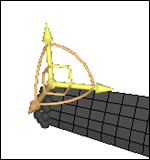
| 22. | Create a new manipulator by clicking new manip and selecting one or more moving nodes. |
| Note: | The different manipulators may have different selected entities and different parameters, and can be moved independently of one another. |
| 23. | Move a manipulator by clicking a manipulator or simply moving your mouse over a manipulator. HyperMesh updates the panel to the parameters associated to that manipulator. You can change the parameters or the entities associated with them if you desire. |
| 24. | Make manipulators active or inactive by switching the manip:active/manip:inactive toggle. When active, the manipulators morph the model when you move them. When inactive, the manipulators will only change their own position and orientation when you move them. |
Summary
Method 1: The length of the propeller blade increased by 100. The fixed nodes did not move. The affected elements were stretched evenly to maintain element quality. The stretching of the elements took place between the moving nodes and the fixed nodes.
Method 2: The length of the propeller blade increased depending on how you dragged the handles along the three arrows, arcs, or right angles of the manipulator to respectively translate, rotate, or move the nodes. The fixed nodes did not move. The affected elements were stretched evenly to maintain element quality. The stretching of the elements took place between the moving nodes and the fixed nodes.
See Also:
HyperMesh Tutorials


