In this tutorial, you will learn how to:
| • | Load the Abaqus user profile and CAD data |
| • | Mesh all of the surfaces at once, specifying element sizes and element type |
| • | Import an Equivalent FiberSim model |
| • | Define the dummy properties and assign them to the mesh |
| • | Define an orientation for the component |
| • | Use the Ply Realization and distribution table option |
| • | Create/Edit distribution table |
| • | View Ply thickness visualization 3D representation |
Model Files
This exercise uses the B-Pillar.CATPart file, which can be found in <hm.zip>/interfaces/abaqus/. Copy the file(s) from this directory to your working directory.
Exercise
Step 1: Load the Abaqus User Profile and Model
A set of standard user profiles is included in the HyperMesh installation. They include: OptiStruct, RADIOSS, Abaqus, Actran, ANSYS, LS-DYNA, MADYMO, Nastran, PAM-CRASH, PERMAS, and CFD. When you load the user profile, HyperMesh displays the applicable utility menus, removes unused panels, disables unneeded entities in the Find, Mask, Card and Reorder panels, and makes specific adaptations related to the Abaqus solver.
| 1. | Start HyperMesh Desktop. |
| 2. | In the User Profile dialog, set the user profile to Abaqus, Standard3D. |
| 3. | From the menu bar, click File > Import > Geometry. The Import - Geometry tab opens. |
| 4. | Set File type to CATIA. |
| 5. | In the File field, open the B-Pillar.CATPart file. |
| 6. | Click Import. HyperMesh imports geometry data only. |
| Note: | You will import the Ply and Composite data later. |
Step 2: Mesh All the Surfaces at Once, Specifying Element Sizes and Element Type
| 1. | Open the Mesh panel by clicking Mesh > Create > 2D AutoMesh from the menu bar, or pressing F12. |
| 2. | Go to the Size and Bias subpanel. |
| 3. | Click surfs >> displayed. |
| 4. | In the element size = field, enter 5. |
| 5. | Set mesh type to mixed. |
| 6. | Set the mesh mode to interactive (it may currently be on automatic). |
| 7. | Set the elements to surf comp/elements to current comp toggle to elems to current comp. |
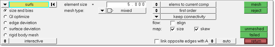
Size and Bias subpanel: Steps 2.3 through 2.7
| 8. | Click mesh. The meshing module opens. |
| Note: | You are now in the Density subpanel of the meshing module. There is node seeding and a number on each surface edge. The number indicates the number of elements that were created along the edge. |
| 9. | Accept the mesh as the final mesh by clicking return. |
| Note: | At this point, you are done using the Mesh panel to mesh the part. The mesh quality is very good. However, you will remain in the meshing module to perform the next steps, which demonstrate how to use various subpanels to interactively control the creation of the mesh. |
| 10. | Click return to go back to the main menu. |
Step 3: Load the Ply Information from FiberSim.
| 1. | From the menu bar, click File > Import > Geometry. The Import - Geometry tab opens. |
| 2. | Set File type to FiberSim. |
| 3. | In the File field, open the bpillar.h5 file. |
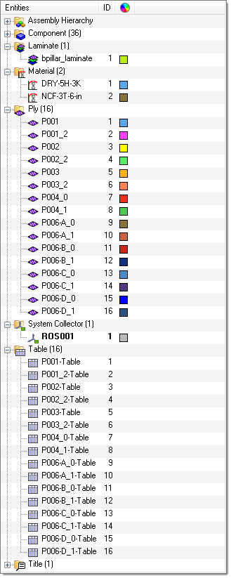
| 4. | Click Import. HyperMesh imports and populates the HyperMesh database with laminate data (ply book and ply stacking data), composite material information, each ply data (triangular elements spanning a single ply), and a coordinate system. |
Step 4: Define the Dummy Properties and Assign them to the Mesh
| 1. | In the Model browser, right-click and select Create > Property from the context menu. HyperMesh creates and opens a property in the Entity Editor. |
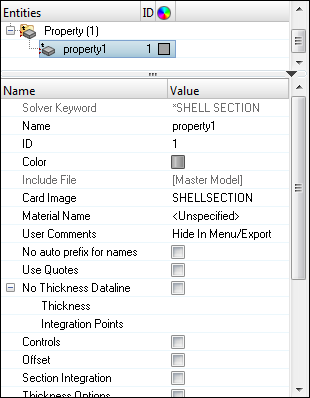
| 2. | For Name, enter Dummy_Prop. |
| 3. | Click the Color icon, and select a color to display the property. |
| 4. | Set Card Image to SHELLSECTION_COMPOSITE. |
Step 5: Define Material Orientation
| 1. | Open the Composites panel by clicking composites in the 2D page. |
| 2. | Go to the material orientation subpanel. |
| 3. | Set the entity selector to props. |
| 5. | Select the property, Dummy_prop. |
| 7. | Double-click system, and then enter the ID of the system which was created while importing the FiberSim model in the id= field. |
| 8. | Set the local axis switch to local 1-axis. |
| Note: | By default, a local axis will automatically be selected when you enter a system ID. |
Step 6: Ply Realization with FiberSim Drape
| 1. | In the Model browser, right-click on the Ply folder and select Realize from the context menu. |
| 2. | In the Ply Realization dialog, set the Realization region selector to Component. |
| 4. | In the panel area, click comps. |
| 5. | Select all of the components. |
| 8. | Set Projection options to FiberSim drape map by proximity method. |
| 9. | Set Search Criterion to Element centroid. |
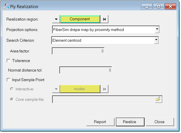
| 10. | Click Realize. HyperMesh takes each FiberSim's ply data and finds the FE elements which are bounded by the ply boundaries, and then transfers the ply directions, draping data, and ply orientation into FE elements. Also, HyperMesh converts geometry plies into FE plies, and creates sets containing FE elements for each ply. |
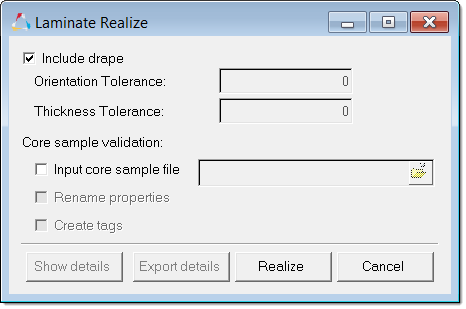
Step 7: Laminate Realize
| 1. | In the Model browser, right-click on the Laminate folder and select Realize from the context menu. |
| 2. | In the Laminate Realize dialog, accept the default settings and click Realize. HyperMesh creates a property for each stack and assigns it to a component. On export the dummy property is ignored. |
Step8: Create/Edit Distribution Table
The variation of element thickness, offset, and drape information is preserved in a distribution table.
| 1. | In the Solver browser, right-click and select Create > Table > *Distribution Drape from the context menu. |
| 2. | In the Create Table dialog, Name field, enter DrapeTable. |
| 4. | Select the elements for which you are creating a distribution table for. |
| 6. | In the Confirm dialog, click Yes to append the selected elements to the table. |
| 7. | In the Thick and Angle columns, enter the corresponding thicknesses and angles for each element. |
| 8. | Click Create. HyperMesh adds the drape table to the Solver browser, Table folder. |
| Note: | Drape data from the FiberSim model is collected in the Table folder. |
| 9. | Optional: Access or edit a table entity by expanding the Table folder, right-clicking on the table entity, and selecting Edit from the context menu. The Edit Table dialog opens with all of the drape information. |
Step 9: Ply Thickness Visualization - 2D Representation
| 1. | On the Visualization toolbar: |
| • | Set the Element Color Mode to By Prop ( ). ). |
| • | Set the Composite Visualization to Composite Layers ( ). ). |
| • | Set the Element Visualization to 2D Detailed Element Representation ( ). ). |
See Also:
HyperMesh Tutorials


