In this tutorial, you will learn how to:
| • | Create an analytical rigid surface (AR surface) |
| • | Define properties of an AR surface |
| • | Create a local coordinate system |
| • | Create a mesh around the AR surface |
An analytical rigid surface in Abaqus is defined as a geometric surface whose motion is governed by a reference node. The TYPE = SEGMENTS, CYLINDER or REVOLUTION parameters in the *SURFACE keyword defines an analytical rigid surface. The two-dimensional profile of a rigid surface is described with straight and curved line segments. This profile can be swept along a generator vector or rotated about an axis to form a three-dimensional surface.
Tools
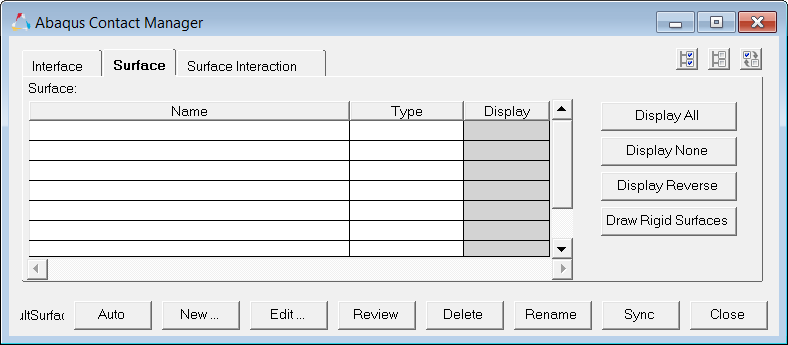
Access the Contact Manager by clicking Tools > Contact Manager from the menu bar. In the Abaqus Contact Manager, you can create, edit, and review the following cards in HyperMesh:
*CONTACT PAIR
|
*PRE-TENSION SECTION
|
*TIE
|
*CONTACT
|
*SURFACE, TYPE = ELEMENT
|
*SURFACE, TYPE = NODE
|
*SURFACE, COMBINE
|
*SURFACE, CROP
|
*SURFACE, TYPE = CUTTING SURFACE
|
*SURFACE, TYPE = CYLINDER, REVOLUTION or SEGMENTS
|
*SURFACE INTERACTION
|
*FRICTION
|
*SURFACE BEHAVIOR
|
*CONTACT DAMPING
|
Model Files
This exercise uses the geometry.hm file, which can be found in <hm.zip>/interfaces/abaqus/. Copy the file(s) from this directory to your working directory.
Exercise
Step 1: Load the Abaqus profile
| 1. | Start HyperMesh Desktop. |
| 2. | In the User Profile dialog, set the user profile to Abaqus, Standard3D. |
| 3. | Open a model file by clicking File > Open > Model from the menu bar, or clicking  on the Standard toolbar. on the Standard toolbar. |
| 4. | In the Open Model dialog, open the geometry.hm file. A model appears in the graphics area. |
Step 2: Create an Analytical Rigid Surface
| 1. | From the menu bar, click Tools > Contact Manager. The Contact Manager opens. |
| 3. | Click New. The Create New Surface dialog opens. |
| 4. | In the Name field, enter a_rigid01. |
| 5. | Set Type to Analytical rigid. |
| 6. | Select a color for the surface. |
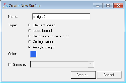
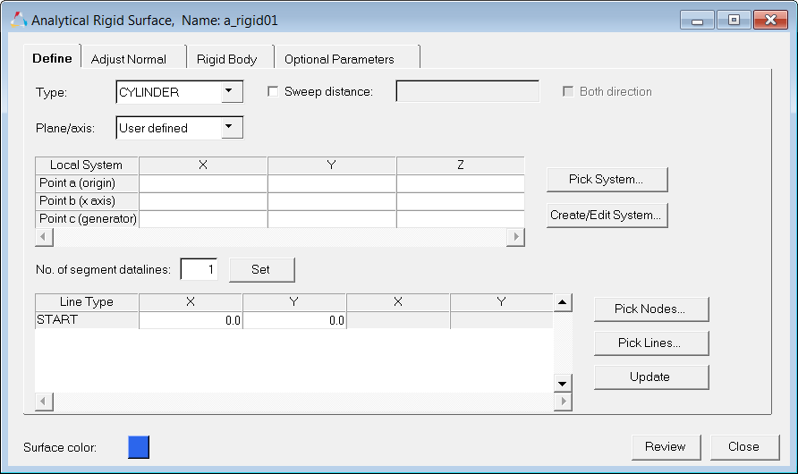
| 7. | Click Create. The Analytical Rigid Surface dialog opens. In this dialog, you can define the analytical rigid surface. |
Step 3: Define the rigid surface type
In this step, you will define the rigid surface type (Cylinder or Revolution).
| Note: | If you are using the 2D template, only the Segments option is available. |
|
| 1. | In the Analytical Rigid Surface dialog, Define tab, set Type to Revolution. |
| Note: | The analytical surface will revolve around the z-axis of the local coordinate system, which is created in the next few steps. |
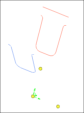
Steps 4 - 6: Create the local coordinate system
Step 4: Create nodes to help define the local coordinate system
| 1. | In HyperMesh, open the Nodes panel by pressing F8. |
| 2. | In the x, y, and z fields, enter 0. |
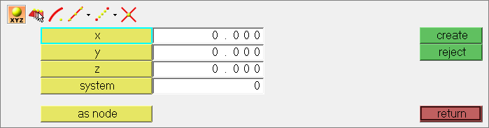
| 3. | Click create. HyperMesh creates a node. |
| Tip: | If the node is not visible, press f to fit the model to the screen. |
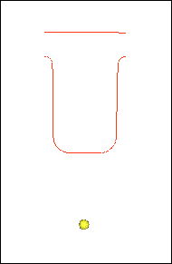
| 4. | Repeat steps 2 and 3 to create nodes in the following locations: (5, 0, 0) and (0, 5, 0). |
These nodes will help define the z-axis and the yz plane of the local coordinate system.
| 5. | Click return to close the panel. |
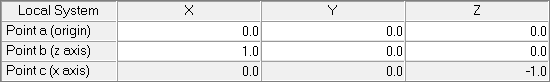
Step 5: Create a rectangular coordinate system
| 1. | In the Analytical Rigid Surface dialog, click Create/Edit System. The System panel opens. |
| 2. | Using the origin selector, select the node at (0,0,0) as the origin node. |
| 3. | Toggle the axis switch to z-axis. |
| 4. | Using the z-axis selector, select the node at (5,0,0). |
| 5. | Using the yz plane selector, select the node at (0,5,0). |
| 6. | Verify that the coordinate system type is set to rectangular. |
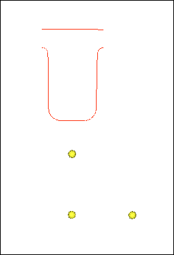
| 7. | Click create. HyperMesh creates a local rectangular system at the origin. |
Step 6: Select the system to be used
| 1. | In the Analytical Rigid System dialog, verify that Plane/axis is set to User defined. |
| 3. | Select the system that was created in Step 7. |
| 4. | In the panel area, click proceed. HyperMesh extracts the coordinates from the system and converts it to a format that Abaqus understands. The local system table populates with numbers. |
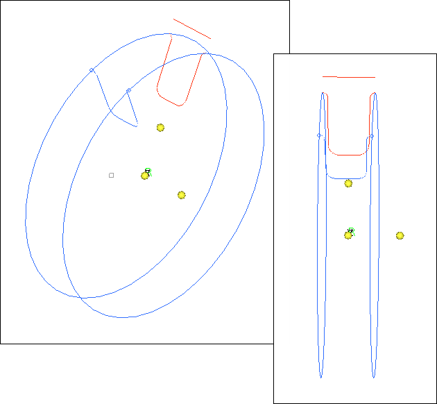
Step 7: Pick the lines to define the analytical rigid surface
For 3D models (type= CYLINDER or REVOLUTION), the local plane, generator vector or the revolution axis can be defined by selecting a HyperMesh system. Alternatively, you can manually input the values in the table.
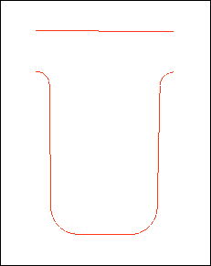
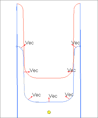
The line segments of the analytical rigid surface's profile can be defined primarily in two ways: by picking nodes or by picking existing line segments.
| • | For the picking nodes option, select the line-segment type, and click the Pick Nodes button to select the corresponding end (or mid) locations from the HyperMesh graphics area. When you return from the node selection panel, the coordinate values of the selected nodes will be transformed into the local plane and appear in the selected cells. In addition, temporary line segments (white color) will be drawn in the HyperMesh graphics area from the picked nodes. You must select two nodes in the correct order for circles and parabolas. |
| • | For the picking existing line segments option, click the Pick Lines button to select some existing lines from the HyperMesh graphics area. These lines must be single curvature and connected, and node1 of a line must be the same as node2 of the previous line. When you return, the segment type and corresponding coordinate values (transformed to the local plane) will appear in the table. |
| Note: | For 2D models (type = SEGMENTS), Abaqus does not require the local plane definition in the data line. However, in HyperMesh, the XY plane must be used for a 2D model (even in axisymmetric analysis). Therefore, the XY plane is selected by default for SEGMENTS. |
|
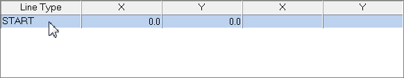
Complete the steps below:
| 1. | In the Analytical Rigid Surface dialog, click START. |
| 3. | Select each line individually starting from one end, going sequentially to the other. Do not select the top horizontal line. |
| Tip: | Zoom in on the model to easily select lines. |
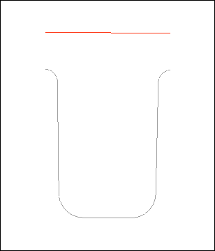
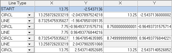
| 4. | In the panel area, click proceed. HyperMesh extracts the line’s data and inputs it into a format that Abaqus understands. The line table populates with numbers. |
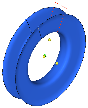
| 5. | Press f to fit the model to the graphics area. |
| 6. | In the Analytical Rigid Surface dialog, select the Revolution angle checkbox and enter 360. |
| 8. | On the Visualization toolbar, shade geometry and surface edges by clicking  . . |
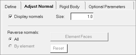
Step 8: Review and reverse the normal
In this step, you will define settings to display the normal direction for each line segment in an analytical rigid surface. The normals of all line segments can be reversed by clicking Reverse.
| 1. | In the Analytical Rigid Surface dialog, click the Adjust Normal tab. |
| 2. | Select the Display normals checkbox. |
| 3. | On the Visualization toolbar, display geometry as a wireframe by clicking  . . |
| 4. | Zoom in on the model to determine the direction from which the contact will take place. The normals are all pointing outward. |
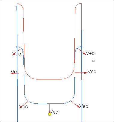
| 5. | In the Analytical Rigid Surface dialog, click Reverse. The normals are now pointing inward. |
When the model is exported as an Abaqus deck, all the cards related to the analytical rigid surface will be exported.
Step 9: Define the *RIGID BODY and reference nodes
An analytical rigid surface must have a *RIGID BODY card with a reference node associated to it. When you create a new rigid surface in the Contact Manager, a *RIGID BODY property collector and an empty component collector (with the same name) are automatically created and linked together. The component collector contains the analytical rigid surface’s geometry and its corresponding elements (if meshed). You can also associate the surface to an existing *RIGID BODY property or create a new one from the Rigid Body tab.
| 1. | In the Analytical Rigid Surface dialog, click the Rigid Body tab. |
| 3. | Select the node at the origin (0,0,0). |
| 4. | In the panel area, click proceed. |
| 5. | Click Update. HyperMesh assigns a reference node to the analytical rigid surface, which will determine its behavior. |
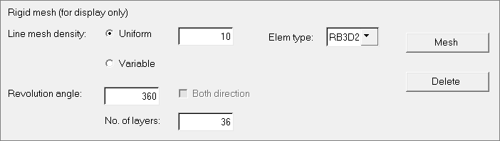
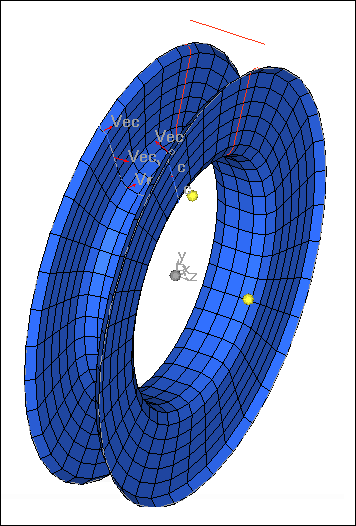
Step 10: Define the rigid mesh for visualization in HyperView
HyperView currently does not support geometric entities such as analytical rigid surfaces. If you mesh the analytical rigid surfaces with rigid elements that point to the same *RIGID BODY card, these elements would not participate in the analysis. They would move with the reference node as a rigid body. These rigid elements would act like a "display body" in Abaqus, and would be imported in HyperView. In the Rigid Body tab you can define this "display body rigid mesh" for visualization.
| 1. | In the Analytical Rigid Surface dialog, Rigid Body tab, enter 10 in the Uniform field. |
| 2. | In the Revolution angle field, enter 360. |
| 3. | In the No. of layers field, enter 36. |
Step 11: Drawing a rigid surface after import
When an Abaqus input file with analytical rigid surfaces is imported into HyperMesh, the surfaces are not displayed automatically. In order to draw the rigid surfaces, you need to open the Abaqus Contact Manager, Surface tab, and click Draw Rigid Surface.
See Also:
HyperMesh Tutorials


