A large portion of HyperMesh functionality is organized into panels. Many panels have common attributes and controls, so once you become familiar with the features of one panel, it is much easier to understand other panels.
In this tutorial, you will learn how to:
| • | Create geometry and organize it into components |
| • | Organize elements into the components |
| • | Identify and delete empty components |
| • | Delete all of the geometry lines |
| • | Reorder the components in a specific order |
| • | Renumber all of the components, starting with ID 1 and incrementing by 1 |
Model Files
This exercise uses the bumper.hm file, which can be found in the hm.zip file. Copy the file(s) from this directory to your working directory.
Exercise
It is recommend that you review the general overview before completing this tutorial.
Step 1: Retrieve the model file, bumper.hm.
| 1. | Start HyperMesh Desktop. |
| 2. | From the menu bar, click File > Open > Model. |
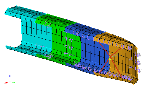
| 3. | In the Open Model dialog, navigate to your working directory and open the bumper.hm model file. A model appears in the graphics area. |
Step 2: Create a component named geometry to hold the model’s geometry.
| 1. | To create a new component, click Collectors > Create > Components from the menu bar, or right-click in the Model browser and select Create > Components from the context menu. |
| 2. | In the Create component dialog, enter geometry in the Name field. |
| 3. | Click the Color icon, and select yellow. |
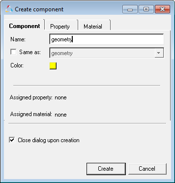
| 4. | Click Create. The Model browser displays the current component collector geometry in bold. |
Step 3: Create two geometry lines and organize them into different components.
| 1. | To open the Lines panel, click Geometry > Create > Lines > Standard Nodes from the menu bar. |
| 2. | Activate the node list selector. |
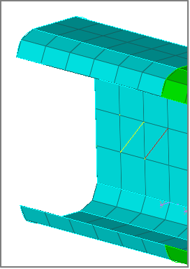
| 3. | In the graphics area, select two opposite and diagonal nodes of the same element as illustrated in the image below: |
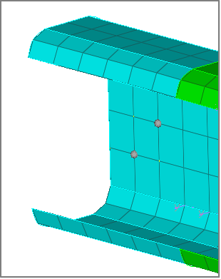
| 4. | Click create. HyperMesh creates a yellow line. |
| Note: | This line is the same color as the geometry component, because it is organized into the current component, geometry. |
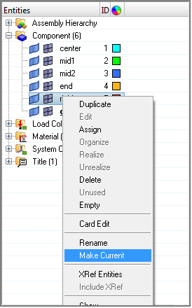
| 5. | In the Model browser, Component folder, right-click on rigid and select Make Current from the context menu. HyperMesh makes the rigid component the active component. |
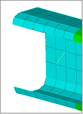
| 6. | In the graphics area, select two opposite and diagonal nodes of the same element, but different than the element selected above. |
| 7. | Click create. HyperMesh creates a red line. |
| Note: | This line is the same color the rigid component, because it is organized into the current component, rigid. |
| 8. | To exit the panel, click return. |
Step 4: Move all of the model’s geometry surfaces into the component, geometry.
| 1. | To open the Organize panel, click Geometry > Organize > Surfaces from the menu bar. |
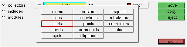
| 2. | To go to the Collectors subpanel, click collectors. |
| 3. | Click  on the entity selector, and select surfs from the list of entities that can be collected. The entity selector is now set to surfs. on the entity selector, and select surfs from the list of entities that can be collected. The entity selector is now set to surfs. |
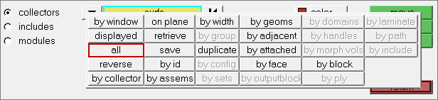
| 4. | Click surfs >> all. HyperMesh highlights all of the displayed surfaces in white, which indicates they are selected. |
| Note: | If there are surfaces that are not displayed, HyperMesh still selects them because you selected surfs >> all. |
| 6. | From the list of components, select geometry. |
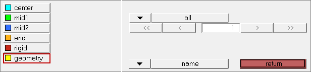
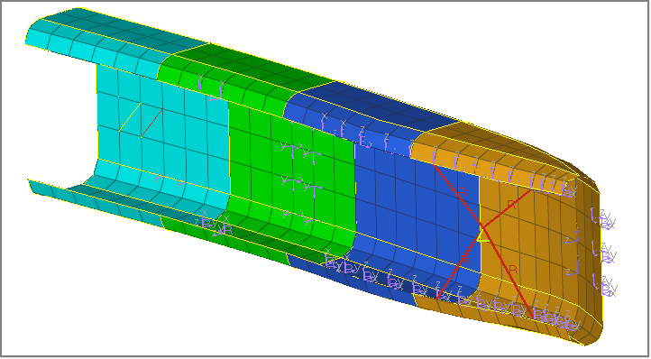
| 7. | Click move. Hypermesh moves the selected surfaces into the geometry component, and colors the geometric entities yellow to match the component color. |
Step 5: Move all the model’s shell elements (quads and trias) into the component, center.
In this step, you should still be in the Organize panel, collectors subpanel.
| 1. | Click on the entity selector, and select elems from the list of entities that can be collected. The entity selector is now set to elems. |
| 2. | Click elems >> by collector. |
| 3. | Select the components: mid1, mid2, and end. |
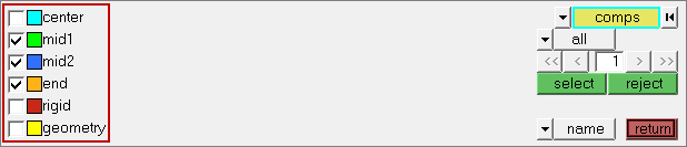
| 4. | Optional: To select a component in the graphics area, left-click on it. A check mark appears in the check box of the component you selected in the panel area. |
| 5. | Optional: To unselect a component, right-click its check box in the panel area, or right-click on it in the graphics area. |
| 6. | To complete your component selection, click select. |
| 7. | Click dest component =. |
| 8. | Select the component center. |
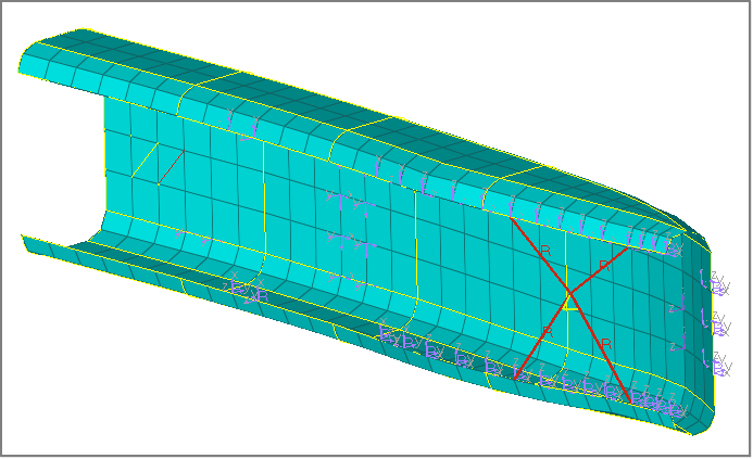
| 9. | Click move. HyperMesh moves the elements in the selected components into the center component, and colors all of the shell elements cyan blue to match the component color. |
| 10. | To exit the panel, click return. |
Step 6: Rename the component center to shells.
| 1. | In the Model browser, Component folder, right-click on center and select Rename from the context menu. |
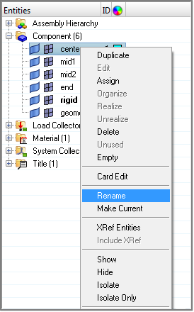
| 2. | In the editable field, rename the component shells and then press Enter. |
Step 7: Identify and delete all of the empty components.
| 1. | To open the Delete panel, press F2. |
| 2. | Set the entity selector to comps. |
| 3. | Click preview empty. The Status bar displays a message that says, "3 entities are empty." |
| Note: | The empty entities are the mid1, mid2, and end components that no longer have elements in them. |
| 4. | Click comps. HyperMesh displays a complete list of the model’s components. |
| Note: | The empty components are indicated with a selected check box. |
| 5. | To return to the Delete panel, click return. |
| 6. | Click delete entity. The Status bar displays a message that says, "Deleted 3 comps 336 elems 28 surfs" |
Step 8: Delete all the geometry lines in the model.
In this step, you should still be in the Delete panel.
| 1. | Set the entity selector to lines. |
| 3. | Click delete entity. HyperMesh deletes the two lines you created earlier. |
| 4. | To exit the Delete panel, click return. |
Step 9: Move the component, geometry, to the front in the components list.
| 1. | To open the Reorder panel, click Collectors > Reorder > Components from the menu bar. |
| 2. | Click comps. HyperMesh displays a complete list of the model’s components. |
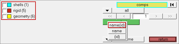
| 3. | On the right side of the panel, click the bottom switch and select name(id). HyperMesh displays the IDs for each component next to its name. The ID for shells is 1, the ID for rigid is 5, and the ID for geometry is 6. |
| 4. | Select the component, geometry. |
| 5. | To complete your selection, click select. |
| 6. | Under move to, select front. |
| 7. | Click reorder. HyperMesh applies the reorder function to the component, geometry. |
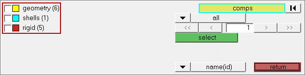
| 8. | To review the reordered list of components, click comps. |
| Note: | The component, geometry, is at the top of the list. However, it still has the same ID, (6). |
| 9. | To exit the panel, click return. |
Step 10: Renumber the components to be the same as their position in the list.
| 1. | To open the Renumber panel, click Collectors > Renumber > Components from the menu bar. |
| 2. | Go to the single subpanel. |
| 3. | Set the entity selector to comps. |
| 4. | Click comps. HyperMesh displays a complete list of the model’s components. |
| 5. | On the right side of the panel, click comps >> all. |
| 6. | To complete your selection, click select. |
| 7. | In the start with = field, enter 1. |
| 8. | In the increment by = field, enter 1. |
| 9. | In the offset = field, enter 0. |
| 10. | Click renumber. HyperMesh renumbers the components. |
| 11. | To review the renumbered list of components, click comps. |
| Note: | The components are numbered according to their position in the list. Set the view to name(id) to see the numbers. |

| 12. | To exit the panel, click return. |
| Note: | Having components with IDs that do not reflect their position in the model’s list of components will not result in errors. However, having components with IDs that do reflect their position in the model’s list of components can be helpful for organizational purposes. |
Step 11: Create an assembly containing the components, shells and rigid.
| 1. | In the Model browser, right-click and select Create > Assembly from the context menu. |
| 2. | In the Create Assembly dialog, enter elements in the Name field. |
| 3. | Select a Color for the assembly. |
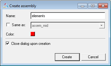
| 4. | Click Create. HyperMesh creates the assembly. |
| 5. | In the Model browser, Component folder, select rigid and shells. |
| Tip: | To select multiple components, press Ctrl + left-click. |
| 6. | To add the selected components to the elements assembly, drag the components, using the left mouse button, over the elements assembly until it highlights. |
Step 12: Create a load collector named constraints.
| 1. | To create a load collector, click Collectors > Create > Load Collectors from the menu bar, or right-click in the Model browser and select Create > Load Collector from the context menu. |
| 2. | In the Create Load Collector dialog, enter constraints in the Name field. |
| 3. | Click the Color icon, and select red. |
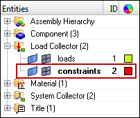
| 4. | Click Create. HyperMesh creates the load collector, and the Status bar displays a message that says, "Load collector created". |
| Note: | The constraints load collector is displayed in bold in the Model browser, which indicates that it is the active load collector. Any loads that are created will be organized into this load collector. |
Step 13: Move the model’s one constraint into the load collector, constraints.
The existing load collector, loads, contains several forces and one constraint. In this step, you will use the Organize panel is to move the one constraint in the load collector, constraints.
| 1. | To open the Organize panel, click Collectors > Organize > Load Collectors from the menu bar. |
| 2. | Go to the collectors subpanel. |
| 3. | Set the entity selector to loads. |
| 4. | Select loads >> by config. |
| 5. | Click config =, and select const. |
| 6. | In the center of the panel, toggle from displayed to all. |
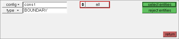
| 8. | Verify that dest component= is set to the load collector, constraints. |
| 9. | Click move. HyperMesh moves the selected constraints into the load collector, constraints. |
Step 14: Create a component from the Model Browser.
| 1. | In the Model browser, right-click and select Create > Component from the context menu. |
| 2. | In the Create Component dialog, enter component1 in the Name field. |
| 3. | Click the Color icon, and select pink. |
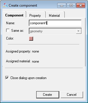
| 4. | Click Create. HyperMesh creates the component, and appends it to the list. |
| 5. | In the Model browser, expand the Components folder to see that component1 is boldfaced in the list, which indicates that it is the current component. |
Step 15: Review the existing assembly elements from the Model Browser.
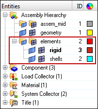
| 1. | In the Model browser, expand the Assembly Hierarchy folder and then expand the elements assembly folder. It contains two components, rigid and shells. |
| Note: | Use can use the Assemblies panel to add components from one assembly to another assembly. The Model browser does not allow you to do this, but you can create assemblies from it. |
Step 16: Add the components, geometry and component1, to the assembly, assem_mid, using the Model browser.
| 1. | In the Model browser, select the geometry and component1 components. |
| Tip: | To select multiple items in the Model browser one at a time, press and hold Ctrl and then left-click the items. If you wish to select multiple items in the Model browser at once, left-click the first item, press and hold SHIFT, and then left-click the last item in the list. |
| 2. | To add the selected components to the assem_mid assembly, drag the components, using the left mouse button, over the assem_mid assembly until it highlights. |
Step 17: Rename assem_mid to assem_geom in the Model browser.
| 1. | In the Model browser, Assembly folder, right-click on assem_mid and select Rename from the context menu. |
| 2. | In the editable field, rename the assembly assem_geom and then press Enter. |
Step 18: Delete component1 from the Model Browser.
| 1. | In the Model browser, right-click on component1 and select Delete from the context menu. |
| 2. | In the HyperMesh dialog, click Yes to confirm that you wish to delete the component. HyperMesh deletes component1. |
Note: In the Model browser, there is no longer a boldfaced component name. This indicates that there is no current component specified.
Step 19: Set the current component from the Model Browser.
| 1. | In the Model browser, Component folder, right-click on shells and select Make Current from the context menu. |
| Note: | The shells component name is boldfaced. |
See Also:
HyperMesh Tutorials


