A large portion of HyperMesh functionality is organized into panels. Many panels have common attributes and controls, so once you become familiar with the features of one panel, it is much easier to understand other panels.
In this tutorial, you will learn how to:
| • | Use the entity selector and the extended entity selection menu to select and unselect nodes and elements from the graphics area. |
| • | Use the orientation selector to define vectors along which to translate nodes and elements. |
| • | Switch between different entities to select and methods to define vectors. |
| • | Toggle between two options. |
| • | Enter, copy and paste, and calculate numbers. |
| • | Use the rapid menu functionality to execute commands with the mouse buttons rather than clicking buttons. |
| • | Interrupt, but not exit, a panel to go to another panel using the keyboard function keys. |
Model Files
This exercise uses the bumper.hm file, which can be found in the hm.zip file. Copy the file(s) from this directory to your working directory.
Exercise
Step 1: Open and view the model file, bumper.hm.
| 1. | Start HyperMesh Desktop. |
| 2. | From the menu bar, click File > Open > Model. |
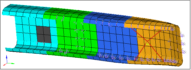
| 3. | In the Open Model dialog, navigate to your working directory and open the bumper.hm model file. A model appears in the graphics area. |
Step 2: In the Translate panel, select nodes from the graphics area.
| 1. | To open the Translate panel, click Mesh > Translate > Nodes from the menu bar. |
| 2. | Click the entity selector to active it. |
| Note: | The cyan border around the entity selector indicates that it is active. |

| 3. | Optional: If necessary, click  on the Visualization toolbar to change the element view style to wireframe. on the Visualization toolbar to change the element view style to wireframe. |
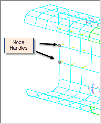
| 4. | In the graphics area, left-click on the corners of the elements to select a few nodes. HyperMesh positions a small, white node at each element corner you select. |
| 5. | To reset the selection of nodes, click  on the entity selector. on the entity selector. |
Step 3: Select and unselect elements from the graphics area.
| 1. | Click  on the entity selector, and select elems from the list of entities that can be translated. The entity selector is now set to elems. on the entity selector, and select elems from the list of entities that can be translated. The entity selector is now set to elems. |

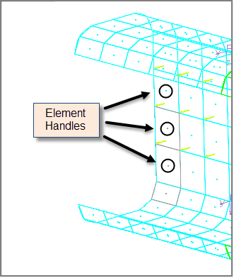
| 2. | In the graphics area, left-click on the element handles (the dot at the element's center) to select several elements. HyperMesh highlights the elements you select in white. |
| 3. | To unselect an element, right-click on the element handle in the graphics area. |
Step 4: Select and unselect elements using the quick window selection method.
| 1. | Verify that the entity selector is active and set to elems. |
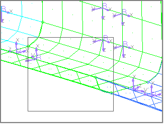
| 2. | In the graphics area, press SHIFT, left-click, and draw a rectangular window around a few elements. HyperMesh selects all of the element handles inside of the rectangular window you drew. |
| 3. | To unselect the elements, press SHIFT, right-click, and draw a rectangular window around the selected elements. |
| 4. | In the graphics area, press SHIFT and left-click. The Quick window pop-up menu appears, containing eight icons. |
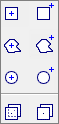
| 5. | Still pressing SHIFT, click  , and draw a polygon window around a few unselected elements. , and draw a polygon window around a few unselected elements. |
| 6. | Release the SHIFT key and mouse button. HyperMesh selects all of the element handles inside of the polygon window. |
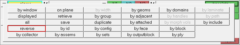
Step 5: Select and unselect elements by using the extended entity selection menu.
| 1. | Click elems >> reverse. HyperMesh unselects the elements that you selected, and selects the elements that were not selected. |
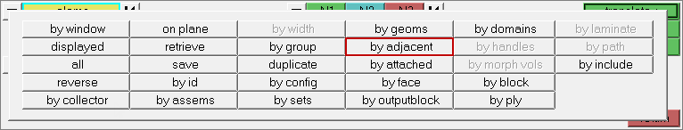
| 2. | Click elems >> by adjacent. HyperMesh selects the elements that are adjacent to the selected elements. |
Step 6: Shade the elements, reset the selection, and select a few adjacent elements.
| 1. | On the Visualization toolbar, click  . HyperMesh displays the elements in shaded mode, rather than wireframe mode. . HyperMesh displays the elements in shaded mode, rather than wireframe mode. |
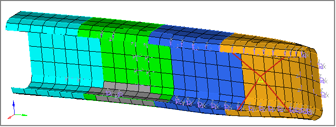
| 2. | To clear the selection of elems, click on the entity selector. |
| 3. | Using the entity selector, select a few elements that are adjacent to each other in the graphics area. |
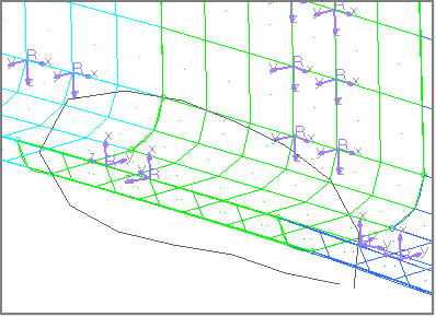
Step 7: Specify a direction vector (N1 and N2 only) along which to translate the selected elements.
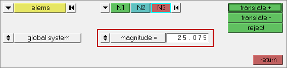
| 1. | On the orientation selector, click and select N1, N2, N3 from the list of vector and plane options, which define the direction in which to translate the selected elements. |

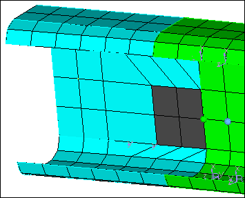
| 2. | To activate the N1 selector, click  . . |
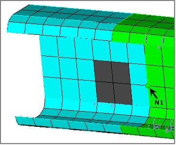
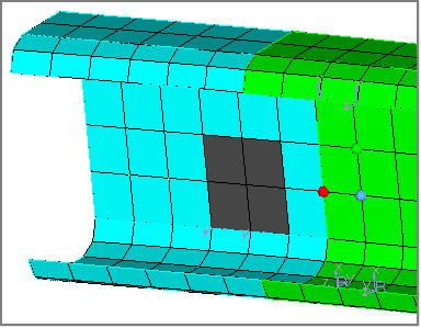
| Note: | The cyan border around the N1 selector indicates that it is active. Since the entity selector is no longer active, HyperMesh changes the color of the selected elements in the graphics area to gray. |
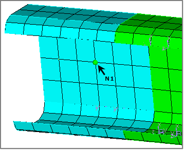
| 3. | In the graphics area, select any node for N1. HyperMesh highlights the selected node in green, and the active selector advances to N2 in the Translate panel. |
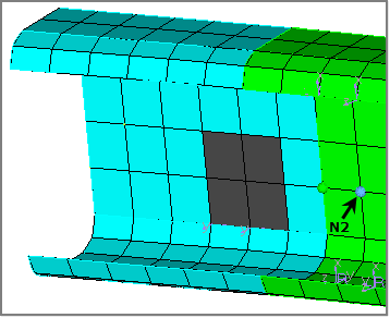
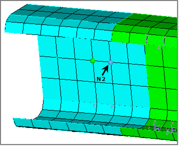
| 4. | In the graphics area, select a node near N1 for N2. HyperMesh highlights the selected node in blue, and the active selector advances to N3 in the Translate panel. |
| Note: | For this tutorial, you do not need to select a node for N3. Selecting N1 and N2 defines a vector for the direction of translation. This vector goes from N1 towards N2. Selecting N3 defines a plane. The direction of translation is the positive direction of the vector normal to the plane. The positive direction is determined by the right-hand rule. |
Step 8: Specify a distance to translate the selected elements and then translate them.
| 1. | Click the second toggle and select magnitude = N2-N1. |
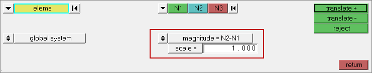
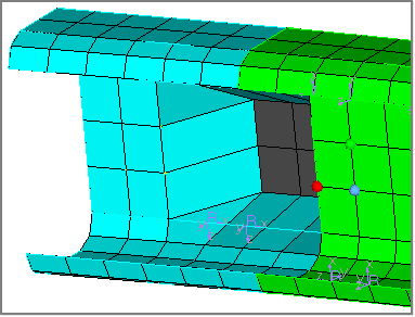
| 2. | Click translate+. HyperMesh translates the selected elements in the N1 to N2 direction by N2-N1 units in the graphics area. |
| Note: | HyperMesh places a thick black border around translate+, which indicates that it is a rapid menu button. |
| 3. | Instead of clicking translate+, middle-mouse click. HyperMesh translates the selected elements again by N2-N1 units. |
| 4. | Click translate- twice. HyperMesh translates the selected elements in the negative N1-N2 vector direction, and restores them to their initial position. |
Step 9: Measure the distance between two nodes.
| 1. | To interrupt, but not exit the Translate panel and go to the Distance panel on the Geom page, press F4. |
| Note: | The graphics area is currently not displaying the elements and nodes that you selected in the Translate panel, however, they are still selected. When you return to the Translate panel, they will reappear. |
| 2. | In the Distance panel, click two nodes. The N1 selector is active. |
| 3. | In the graphics area, select any node for N1. HyperMesh highlights the selected node in green, and the active selector advances to N2. |
| 4. | In the graphics area, select a node near N1 for N2. The distance between N1 and N2 appears in the distance = field. |
| 5. | In the distance = field, highlight the value. |
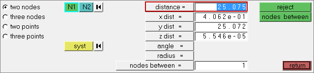
| 6. | To copy the value, press CTRL + C. |
| 7. | To return to the Translate panel, click return. The graphics area displays the elements and nodes you selected earlier in the Translate panel. |
Step 10: Specify a distance to translate the selected elements and then translate them.
| 1. | Click the second toggle and select magnitude =. |
| 2. | In the magnitude = field, highlight the value. |
| 3. | To paste the distance= value that you copied from the Distance panel, press CTRL + V. |
| 4. | Click translate+. HyperMesh translates the selected elements in the direction from N1 to N2 by the number of units specified in the magnitude = field. |
| 5. | Click translate- once. HyperMesh translates the selected elements in the negative N1-N2 vector direction, and restores them to their initial position. |
Step 11: Calculate 5.5 * 10.5 and specify the resulting value for magnitude =.
| 1. | In the magnitude= field, right-click. The HyperMesh calculator appears. |
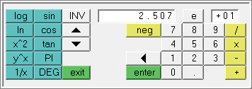
| 2. | Click 5 . 5 (in that order). |
| 4. | Click 10 . 5 (in that order). |
| 5. | Click X. The calculator displays a calculated value of 57.75. |
| 6. | Click exit. The calculator closes and 57.75 appears in the magnitude = field. |
| 7. | Optional: To enter a value in the magnitude = field, left-click in the field to highlight the current value, then enter a new value. |
Step 12: Specify a new vector and translate the elements again.
| 1. | To reset the direction of the translated elements, click on the direction selector. N1 becomes the active selector. |
| 2. | In the graphics area, select three nodes for N1, N2, N3 to define a plane. |
| 3. | Click translate+ or middle-mouse click. HyperMesh translates the elements 57.75 units in the positive direction normal to the defined plane. |
| 4. | To exit the panel, click return. |
Step 13 (Optional): Save your work.
| 1. | When you have completed all of the exercises in this tutorial, click File > Save > Model from the menu bar. |
See Also:
HyperMesh Tutorials


