In this tutorial, you will learn about:
| • | Checking tetra element quality |
| • | Remeshing tetra elements |
HyperMesh provides two methods for generating a tetrahedral element mesh. The volume tetra mesher works directly with surface or solid geometry to automatically generate a tetrahedral mesh without further interaction with you. Even with complex geometry, this method can often generate a high quality tetra mesh quickly and easily.
The standard tetra mesher requires a surface mesh of tria or quad elements as input, and then provides you with a number of options to control the resulting tetrahedral mesh. This offers a great deal of control over the tetrahedral mesh, and provides the means to generate a tetrahedral mesh for even the most complex models.
You can use the Tetramesh panel to fill an enclosed volume with first or second order tetrahedral elements. A region is considered enclosed if it is entirely bounded by a shell mesh (tria or quad elements), where each element has material on one side and open space on the other.
Model Files
This exercise uses the housing.hm file, which can be found in the hm.zip file. Copy the file(s) from this directory to your working directory.
Exercise
Step 1: Retrieve and view the model file.
| 1. | Start HyperMesh Desktop. |
| 2. | From the menu bar, click File > Open > Model. |
| 3. | In the Open Model dialog, open the housing.hm model file. |
| 4. | Observe the model using the different visual options available in HyperMesh (rotation, zooming, and so on). Only the geometry in the component cover is currently displayed. The file contains two parts defined by a volume of surfaces. The geometry has been cleaned such that surface connectivity is proper and surface edges that would cause sliver elements are suppressed. |
Step 2: Use the volume tetra mesher and equilateral triangles to create a tetra mesh for the cover.
| 1. | Open the Tetramesh panel by clicking Mesh > Create > Tetra Mesh from the menu bar. |
| 2. | Go to the Volume tetra subpanel. |
| 3. | Set the Enclosed volume selector to surfs . |
| 4. | Select one of the surfaces in the model. |
| 5. | Verify that the 2D type is set to trias and the 3D type is set to tetras. |
These options control the type of elements that HyperMesh creates for the surface mesh and solid mesh of the part.
| 6. | Verify that the toggle is set to Elems to Current Comp. |
This option allows HyperMesh to place the newly created elements in the current component collector.
| 7. | Verify that the Use curvature and Use proximity checkboxes are clear. |
| 8. | In the Element size field, enter 10. |
| 9. | Click mesh. HyperMesh creates the tetra mesh. |
| 10. | If the model's mesh lines and elements are not shaded, click  on the Visualization toolbar. on the Visualization toolbar. |
| 11. | Inspect the mesh pattern that the volume tetra mesher created. |
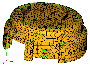
Tetra mesh created in the volume tetra subpanel using equilateral triangles (2D: trias)
| 12. | Reject the mesh by clicking reject. |
Step 3: Use the volume tetra mesher and right triangles to create a tetra mesh for the cover.
In this step, you should still be in the Volume tetra subpanel.
| 1. | Select one of the surfaces in the model. |
| 2. | Set the 2D type to R-trias. |
| 3. | Click mesh. HyperMesh creates the tetra mesh. |
| 4. | Inspect the mesh pattern that the volume tetra mesher created and compare it to the first mesh that you created. |
| Note: | The 2D type: R-trias setting tends to create tetra elements with triangular faces that are right triangles (90-45-45 angles), while the 2D type: trias setting tends to create equilateral triangles (60-60-60 angles). |

Tetra mesh from the volume tetra subpanel and right triangles (2D type: R-trias)
| 5. | Reject the mesh by clicking reject. |
Step 4: Use the volume tetra mesher to create a tetra mesh with more elements along curved surfaces.
In this step, you should still be in the Volume tetra subpanel.
| 1. | Select one of the surfaces in the model. |
| 2. | Select the Use curvature checkbox. |
The option causes more elements to be created along areas of high surface curvature. Thus, curved areas such as fillets will have more and smaller elements, which capture those features with higher resolution.
| 3. | In the Min elem size field, enter 1.0. |
| 4. | Verify that the Feature angle is set to 30. |
| 5. | Click mesh. HyperMesh creates the tetra mesh. |
| 6. | Inspect the mesh pattern that the volume tetra mesher created and compare it to the previous meshes you created. You can see that more small elements are created around the fillets. |
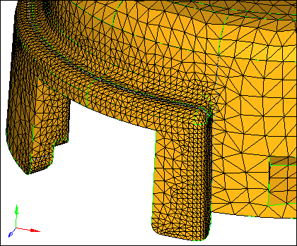
Tetra mesh from the volume tetra subpanel with the use curvature check box selected
| 7. | Reject the mesh by clicking reject. |
Step 5: Use the volume tetra mesher to create a tetra mesh with more elements around small features.
In this step, you should still be in the Volume tetra subpanel.
| 1. | Select one of the surfaces in the model. |
| 2. | Select the Use proximity checkbox. |
This option causes the mesh to be refined in areas where surfaces are smaller, which results in a nice transition from small elements on small surfaces to larger elements on larger, adjacent surfaces.
| 3. | Click mesh. HyperMesh creates the tetra mesh. |
| 4. | Inspect the mesh pattern that the volume tetra mesher created and compare it to the previous meshes you created. You can see that more elements are created around the surfaces with small angles. |
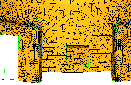
Tetra mesh from the volume tetra subpanel with the Use curvature and Use proximity check boxes selected.
Step 6: Prepare the display to tetra mesh the hub component using the standard tetra mesher.
| 1. | In the Model browser, turn off the display of every component's geometry except for hub. |
| 2. | Turn off the display of every component's elements except for hub and tetras. |
| Note: | There are tria shell elements in the hub component, and no elements in the tetras component. |
| 3. | Return to the main menu by clicking return. |
Step 7 (Optional): Review the connectivity and quality of the tria mesh to validate its integrity for the standard tetra mesher.
In this step you will use the Edges and Check Elems panels to make sure that there are no free edges or very small angles in the tria shell mesh.
| 1. | Open the Edges panel by clicking Mesh > Check > Components > Edges from the menu bar. |
| 2. | Verify that the entity selector is set to comps. |
| 3. | Select a tria element on the hub component. HyperMesh highlights the entire component. |
| 4. | Click find edges. The status bar displays a message that reads, "No edges were found. Selected elements may enclose a volume." |
| Note: | The tetra mesher requires a closed volume of shell elements. |
| 5. | Return to the main menu by clicking return. |
| 6. | Open the Check Elements panel by clicking Mesh > Check > Elements > Check Elements from the menu bar. |
| 7. | Verify that you are in the 2-d subpanel. |
| 8. | Identify the elements that have an aspect ratio greater than 5. |
Aspect ratio is the ratio of the longest edge of an element to its shortest edge. This check helps you to identify sliver elements. All of the hub’s shell elements pass the check; all of the elements have an aspect ratio less than 5.
| 9. | Identify the tria elements that have an angle less than 20. |
This check helps identify sliver elements. All of the hub’s shell elements pass the check; all the elements have angles greater than 20. The surface mesh is suitable for creating a tetra mesh.
| 10. | Return to the main menu by clicking return. |
Step 8: Create a tetra mesh for the hub using the standard tetra mesher.
| 1. | In the Model browser, Component folder, right-click on tetras and select Make Current from the context menu. |
| 2. | Open the Tetra Mesh panel. |
| 3. | Go to the Tetra mesh subpanel. |
| 4. | Verify that the Float trias/quads to tetra mesh entity selector is set to comps. |
| Note: | By using this entity selector, HyperMesh will swap the diagonal for any pair of surface trias, which will result in a better tetra mesh quality. If you would rather keep the diagonal, see step 8.6. |
| 5. | Select a shell element on the hub component. HyperMesh highlights the entire component. |
| 6. | Optional: Keep the diagonal as is by activating the Fixed trias/quads to tetra mesh entity selector and setting it to comps. |
| 7. | Click mesh. HyperMesh generates the tetrahedral elements. |
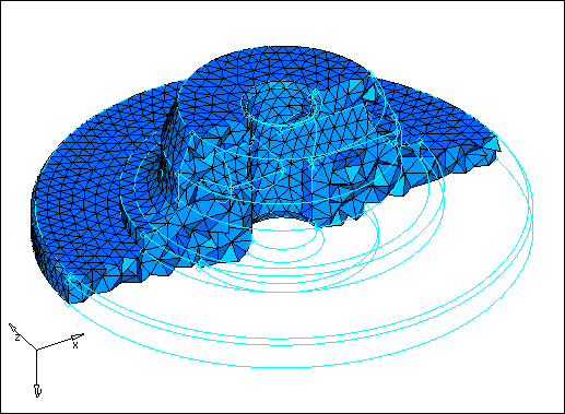
Cut-away view of tetrahedral elements using the Masks panel
Step 9: Check the quality of the hub’s tetra elements.
| 1. | In the Model browser, only display the tetras component elements. |
| 2. | Open the Check Elements panel. |
| 3. | Go to the 3-d subpanel. |
| 4. | Identify the smallest element length among the displayed elements. If the minimum length is acceptable for a target element size of 5.0, then no further action is necessary. |
| 5. | Identify the smallest angle (tria faces: min angle) among the displayed elements. If the minimum tria face angle is no less than 10°, then the mesh quality should be acceptable. |
| 6. | Identify elements that have a tet collapse smaller than 0.3. The status bar indicates that three elements have a tetra collapse smaller than 0.3. |
| Note: | The tet collapse criteria is a normalized volume check for tetrahedral elements. A value of 1 indicates a perfectly formed element with maximum possible volume. A value of 0 indicates a completely collapsed element with no volume. |
Step 10: Isolate the element with the tetra collapse smaller than 0.2 and find the elements surrounding it.
In this step, you should still be in the Check Elements panel.
| 1. | With 0.3 still specified in the tet collapse< field, click tet collapse. |
| 2. | Click save failed. HyperMesh saves the elements that failed the tetra collapse check in the user mark. |
| Note: | You can retrieve the saved elements that failed the check from any panel by selecting retrieve in the extended selection menu. |
| 3. | Return to the main menu by clicking return. |
| 4. | Open the Mask panel by pressing F5. |
| 5. | Set the entity selector to elems. |
| 6. | Click elems >> retrieve. HyperMesh retrieves the elements that were saved in the Check Elements panel. |
| 7. | Click elems >> reverse. |
| 8. | Click mask. HyperMesh masks the elements and displays the three tetra element that failed the tetra collapse check. |
| 9. | Return to the main menu by clicking return. |
| 10. | On the Display toolbar, click  . HyperMesh identifies and displays the layer of elements that are attached to the three displayed element. . HyperMesh identifies and displays the layer of elements that are attached to the three displayed element. |
| 11. | Click two more times. HyperMesh identifies and displays the layers of elements that are attached to the displayed elements. |
| Note: | You can duplicate the functionality of unmask adjacent using the Find panel, find attached subpanel in the Tool page. |
| 12. | In the Model browser, turn off the display of the hub elements that were unmasked. |
Step 11: Remesh the hub’s displayed tetra elements to improve their tetra collapse.
| 1. | Open the Tetra Mesh panel. |
| 2. | Go to the Tetra remesh subpanel. |
| 3. | Click 3D elements: elems >> displayed. |
| 4. | Click remesh. HyperMesh regenerates this area of the mesh. |
| 5. | Return to the main menu by clicking return. |
| 6. | Open the Check Elements panel. |
| 7. | Find out if the tetra collapse has improved for the displayed elements by clicking tet collapse. The status bar indicates that the minimum tetra collapse is larger than the value reported before the tetra elements were remeshed. |
| 8. | Return to the main menu by clicking return. |
Step 12 (Optional): Save your work.
Now that the tetra mesh is complete, it is a good time to save the model.
| 1. | From the menu bar, click File > Save > Model. |
Summary
You have created a tetra mesh for both parts in the model using different tetra meshing procedures. Either method can be used to mesh parts, depending on the needs of the analysis. The tetra remesh function was used in this tutorial to show how to quickly fix the quality of tetra elements.
See Also:
HyperMesh Tutorials


