In this tutorial, you will learn how to:
| • | Create solids using different functions |
| • | Check and fix improper model connectivity |
For some analyses, it is desirable to use a mesh of hexahedral and pentahedral elements. This is especially true for parts which have a large thickness compared to the element size being used, or for parts that have many features and/or changes in thickness. Castings or forgings are good examples.
Model Files
This exercise uses the arm_bracket.hm file, which can be found in the hm.zip file. Copy the file(s) from this directory to your working directory.
Exercise: Creating a Hex-Penta Mesh using Surfaces
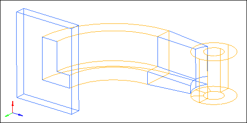
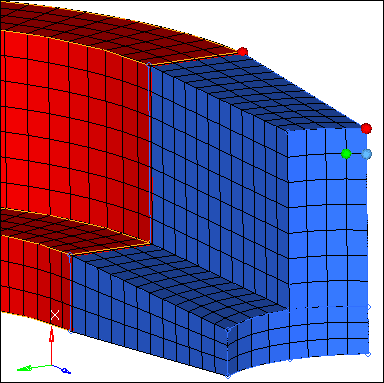
The objective of this exercise is to introduce you to a number of HyperMesh functions that are used to create hexa-penta meshes. The arm_bracket.hm model is organized into four IGES layers, consisting of 1) the base, 2) the first section of the arm, with a constant cross section and curvature, 3) the second section of the arm, with a tapered cross section, and 4) the boss.
Step 1: Retrieve and review model file.
| 1. | Start HyperMesh Desktop. |
| 2. | From the menu bar, click File > Open > Model. |
| 3. | In the Open Model dialog, open the arm_bracket.hm model file. |
Step 2: Mesh the top surface of the base, including the L-shaped surface.
| 1. | In the Model browser, Component folder, right-click on base and select Make Current from the context menu. |
| 2. | Right-click on base again and select Isolate from the from the context menu. HyperMesh hides all of the components except for base. |
| 3. | Open the AutoMesh panel by clicking Mesh > Create > 2D AutoMesh from the menu bar. |
| 4. | Go to the size and bias subpanel. |
| 5. | Shade the model's geometry and surface edges by clicking  on the Visualization toolbar. on the Visualization toolbar. |
| 6. | Verify that the entity selector is set to surfs. |
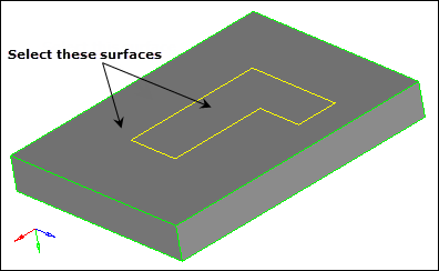
| 7. | Select the surfaces on the top of the base, including the L-shaped surface at the intersection of the base and the arm. |
| 8. | Set the meshing mode to automatic. |
| 9. | In the element size field, enter 10. |
| 10. | Set the mesh type to quads only. |
| 11. | Click mesh. HyperMesh meshes the selected surface. |
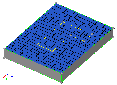
Resulting quad mesh on base surfaces
| 12. | Return to the main menu by clicking return. |
Step 3: Create layers of hex elements for the base.
| 1. | Open the Elem Offset panel by clicking Mesh > Create > 3D Elements > Element Offset from the menu bar. |
| 2. | Go to the solid layers subpanel. |
| 3. | Click elems to offset: elems >> displayed. HyperMesh selects the elements on the base. |
| 4. | In the number of layers = field, enter 5. |
| 5. | In the total thickness = field, enter 25. |
| 6. | Click offset+. HyperMesh creates the hexa mesh. |
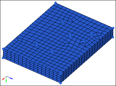
Hex mesh on base
Step 4: Prepare the display for meshing the arm’s curved segment.
| 1. | In the Model browser, Component folder, right-click on arm_curve and select Show from the context menu. |
| 2. | Open the Mask panel by pressing F5. |
| 3. | Click elems >> by config. |
| 4. | Click config= and select the hex8 configuration. |
| 5. | Click select entities. HyperMesh selects all of the elements with a configuration of hex8 in the model. |
| 6. | Click mask. HyperMesh masks the elements. |
| 7. | Return to the main menu by clicking return. |
Step 5: Create a node at the center of the arm radius.
The first segment of the arm can be meshed using the Spin panel. This requires a node to be selected as the center point of rotation. In this step, you will use the distance panel, 3 nodes subpanel to create a node that will be used as the center point of rotation.
| 1. | Open the Distance panel by pressing F4. |
| 2. | Go to the three nodes subpanel. |
| 3. | Verify that the N1 node selector is active. |
| 4. | While pressing the left mouse button, move it over the curved line as indicated in the following image, and then release it when the cursor changes to  . HyperMesh highlights the line. . HyperMesh highlights the line. |
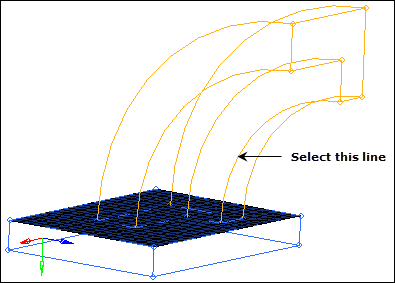
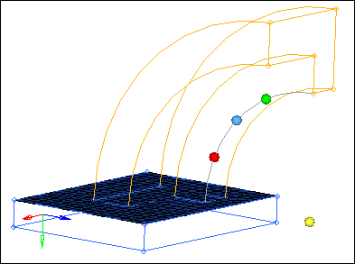
| 5. | Click three locations along the selected line. The active selector advances from N1 to N2 to N3, and HyperMesh create the temporary nodes on the selected curved line of the arm. |
| 6. | Click circle center . HyperMesh creates the node at the center. |
| Note: | You will use this node in the next step when you mesh the arm. |
| 7. | Return to the main menu by clicking return. |
Step 6: Create hexa elements in the curved portion of the arm using spin.
| 1. | In the Model browser, Component folder, right-click on arm_curve and select Make Current from the context menu. |
| 2. | Open the Spin panel by clicking Mesh > Create > 3D Elements > Spin from the menu bar. |
| 3. | Go to the spin elems subpanel. |
| 4. | Click 2d elems: elems >> by window. |
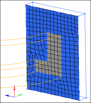
| 5. | Select the plate elements within the L-shaped cross section of the arm as indicated in the following image. |
| 7. | In the angle = field, enter 90 degrees. |
| 8. | Set the orientation vector to x-axis (Y-Z plane). |
| 9. | Select the center node you created in step 5 for the base node (B). |
| 10. | In the on spin = field, enter 24. |
| Note: | This option determines how many layers of hex elements HyperMesh creates when the plate elements are spun. |
| 12. | Return to the main menu by clicking return. |
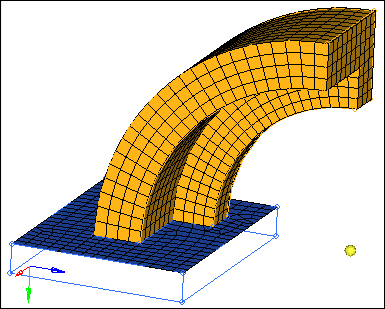
spin panel results
Step 7: Create faces on the hex elements.
| 1. | Open the Faces panel by clicking Mesh > Check > Components > Faces from the menu bar. |
| 2. | Set the entity selector to comps. |
| 3. | Click comps >> arm_curve. |
| 5. | Click find faces. HyperMesh creates 2D shell elements on the free faces of every 3D solid element in the component, and places them in a new component named ^faces. |
| Note: | The ^faces component is created with its visualization set to wireframe, therefore you will not be able to see the new elements right away if the arm_curve component is displayed and in shaded mode. |
| 6. | Shade the model's elements and mesh lines by clicking  on the Visualization toolbar. The graphics area now displays the elements in the ^faces component. on the Visualization toolbar. The graphics area now displays the elements in the ^faces component. |
Step 8: Prepare the display for meshing the second arm segment.
| 1. | From the Model browser, turn on the display of the arm_straight and ^faces components. |
Step 9: Mesh the L-shaped set of surfaces between the arm_straight and boss components.
| 1. | In the Model browser, Component folder, right-click on arm_straight and select Make Current from the context menu. |
| 2. | Open the Automesh panel. |
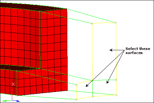
| 3. | Select the three surfaces lying on the intersection between the arm_straight and boss components as indicated in the following image. |
| Note: | These surfaces are all in the arm_straight component. |
| 4. | Set the meshing mode to interactive. |
| 5. | Click mesh. The meshing module opens. |
| 6. | Go to the density subpanel. |
| 7. | Adjust the density of each edge to obtain a mesh that matches the following image. |
| Note: | This mesh pattern matches the mesh pattern at the intersection of the two arm segments. This is necessary for the next step. |
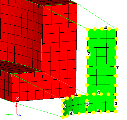
Densities to correspond to the mesh on the end face
| 8. | Click mesh. HyperMesh updates the mesh density. |
| 9. | Create the elements and go back to the main menu by clicking return twice. |
Step 10: Use linear solid to build the mesh between the two sets of shell elements.
| 1. | Open the Linear Solid panel by clicking Mesh > Create > 3D Elements > Linear 3D from the menu bar. |
| 2. | Activate the from: elems selector. |
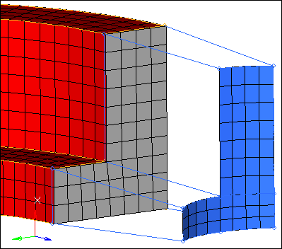
| 3. | Select the ^faces elements lying on the intersection between the first and second arm segments as indicated in the following image. |
| Tip: | Quickly select all of the necessary elements by selecting one of the elements and then clicking from: elems >> by face. |
| 4. | Activate the to: elems selector. |
| 5. | Select the shell elements, between the arm and boss, that you created using the Automesh panel in step 9. |
| 6. | Activate the from: alignment: N1 selector. |
| 7. | Select three nodes on one of the "from elements" that you selected in step 10.3 as indicated in the following image. |
| 8. | Activate the to: alignment: N1 selector. |
| 9. | Select three nodes on the "to element" that corresponds to the "from element" with the three "from nodes" as indicated in the following image. |
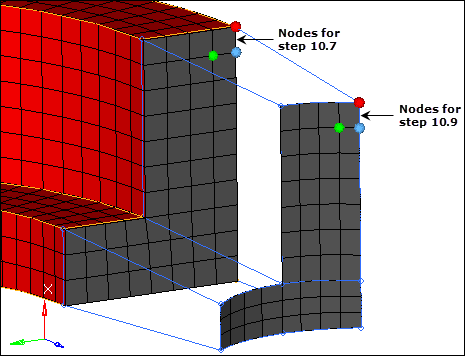
Example selection for alignment nodes
| 10. | In the density = field, enter 12. |
| 11. | Click solids. HyperMesh creates the mesh. |
Linear solid mesh
| 12. | Return to the main menu by clicking return. |
Step 11: Prepare the display for meshing the boss.
| 1. | In the Model browser, Component folder, right-click on boss and select Show from the context menu. |
Step 12: Create a shell mesh on the bottom of the boss.
| 1. | In the Model browser, Component folder, right-click on boss and select Make Current from the context menu. |
| 2. | Open the Automesh panel. |
| 3. | Select the five surfaces on the bottom face of the boss as indicated in the following image. |
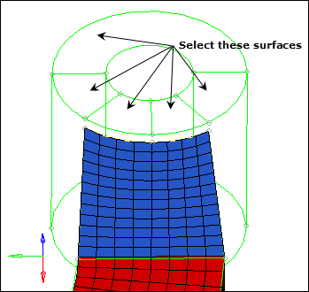
| 4. | Click mesh. The meshing module opens. |
| 5. | Adjust the density of each edge to obtain a mesh that matches the following image. |
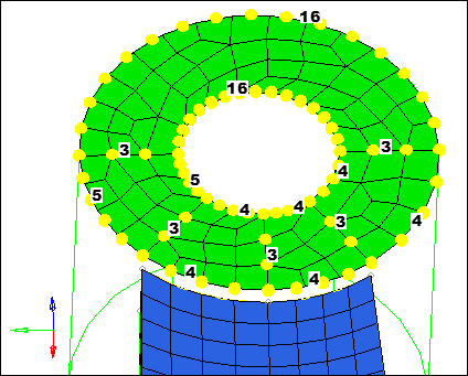
Mesh densities on the bottom of the boss
| 6. | Click mesh. HyperMesh updates the mesh density. |
| 7. | Return to the main menu by clicking return twice. |
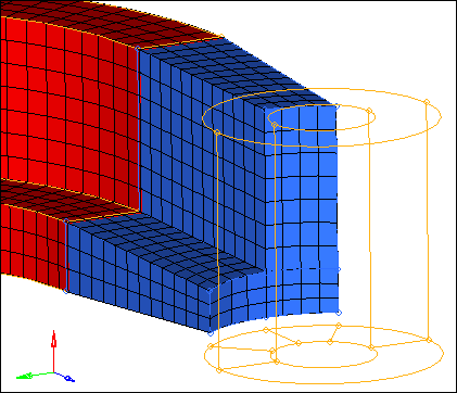
Step 13: Project a node to the bottom face of the boss.
| 1. | Open the Project panel by clicking Mesh > Project > Nodes from the menu bar. |
| 2. | Go to the to line subpanel. |
| 3. | Select the node on the rightmost top vertex as indicated in the following image. |
| 4. | Click nodes >> duplicate. |
| 5. | Activate the to line: line list selector. |
| 6. | Select the line on the boss’ top face as indicated in the following image. |
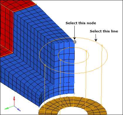
Projecting a node to a line
| 7. | Set the along vector to x- axis. |
| 8. | Click project. The node projects to the line. |
| 9. | Return to the main menu by clicking return. |
Step 14: Generate hexas for the boss using the Solid Map panel.
| 1. | Open the Solid Map panel by clicking Mesh > Create > Solid Map Mesh from the menu bar. |
| 2. | Go to the general subpanel. |
| 3. | Click the source geom switch and select none. |
| 4. | Activate the dest geom: surf selector. |
| 5. | Select the top surface of the boss as indicated in the following image. |
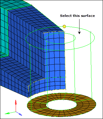
| 6. | Click the along geom switch and select mixed. |
| 7. | Activate the along geom: mixed lines selector. |
| 8. | Select the line indicated in the following image. |
| 9. | Activate the along geom: mixed node path selector. |
| 10. | Select the 13 nodes as indicated in the following image, to define the exact location of the solid element layers. |
| Note: | A total of 13 nodes should be selected, starting at the boss mesh, and then using all of the nodes along the edge of the arm_straight component, ending with the node projected to the top of the boss. |
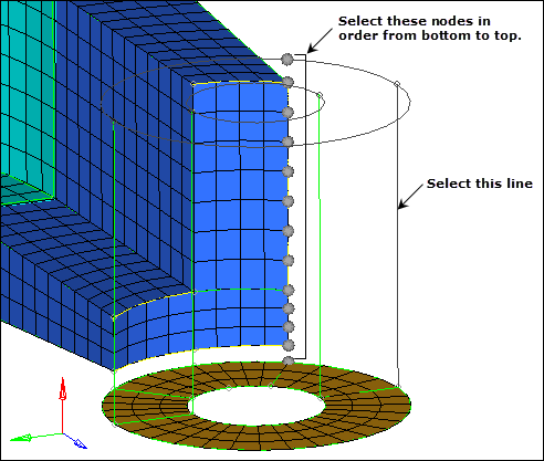
Along nodes for solid map
| 11. | Click elems to drag: elems >> by collector >> boss. |
| 13. | Click mesh. HyperMesh creates the elements and completes the mesh on this part. |
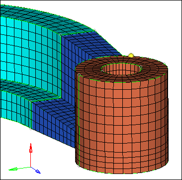
Completed mesh of the arm bracket
| 14. | Return to the main menu by clicking return. |
Step 15 (optional): Check the connectivity of the model.
| 2. | Click comps. HyperMesh displays a list of components. |
| 3. | Select every component from the list, or select comps >> all. |
| 6. | From the Model browser, turn off the geometry display of all components. |
| 7. | Turn off the element display of all components except ^faces. |
| 8. | Exit the the panel by clicking return. |
| 9. | From the Post page, select hidden line. |
| 10. | Select the xz plane and trim plane checkboxes. |
| 11. | Click show plot. HyperMesh displays the faces with a plane cutting the model in half. |
| Note: | This allows you to review the interior of the model. |
| 12. | Click near the cutting plane, hold the left mouse button down, and move your mouse back and forth. The cutting plane moves through the model, allowing you to see if any face elements exist on the interior of the model. |
| Note: | You should see that there are face elements interior to the model, between the boss and arm. You need to perform some corrections on the connectivity. |
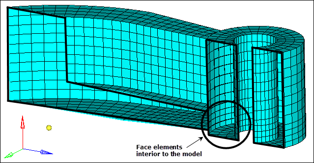
Hidden line view of faces
| 13. | Return to the main menu by clicking return. |
Step 16 (Optional): Correct the connectivity of the model.
| 1. | In the Model browser, display the elements for all of the components except for ^faces. |
| 2. | Display the model's elements as transparent by clicking  on the Visualization toolbar. on the Visualization toolbar. |
| 4. | Set the entity selector to elems. |
| 5. | Click elems >> displayed. |
| 6. | Click preview equiv. HyperMesh highlights coincident nodes on the intersection between the arm and the boss. |
| 7. | Specify a slightly larger value in the tolerance = field, and then click preview equiv. Hypermesh identifies more more coincident nodes on the intersection. |
| 8. | Repeat step 16.7 until all 60 coincident nodes have been found. |
| 9. | Click equivalence. HyperMesh replaces the nodes to the location of the lowest node ID. |
| 10. | Switch all the components to the shaded visual mode. |
Step 17 (Optional): Recheck the connectivity of the model.
Repeat Step 15 to make sure the model is now equivalenced. If you find errors, repeat Step 16.
Step 18 (Optional): Save your work.
Now that the 3D solid mesh has been completed, it is a good time to save your model.
| 1. | From the menu bar, click File > Save > Model. |
See Also:
HyperMesh Tutorials


