In this tutorial, you will learn how to:
| • | Identify shell element connectivity problems |
| • | Correct shell element connectivity problems |
| • | Review the model’s shell elements to ensure connectivity problems were corrected |
| • | Remesh the elements along the rib |
| • | Use element quality Cleanup tools |
Model Files
This exercise uses the cover.hm file, which can be found in the hm.zip file. Copy the file(s) from this directory to your working directory.
Exercise
Step 1: Retrieve and view the HyperMesh model file.
| 1. | Start HyperMesh Desktop. |
| 2. | From the menu bar, click File > Open > Model. |
| 3. | In the Open Model dialog, open the file cover.hm. |
Step 2: Review the model’s free edges to identify shell element connectivity problems.
| 1. | To open the Edges panel, do one of the following: |
| • | From the menu bar, click Mesh > Check > Components > Edges. |
| • | On the Checks toolbar, click  (Edges). (Edges). |
| • | From the main menu, go to the Tool page and click edges. |
| 2. | Set the entity selector to comps. |
| 3. | In the graphics area, select any element. HyperMesh selects the component containing the element you selected. |
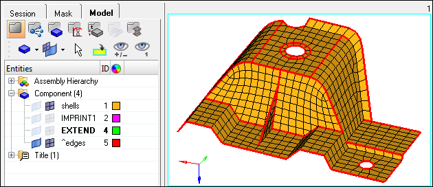
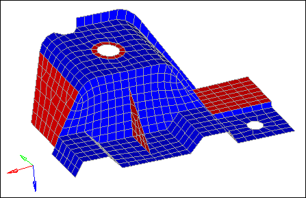
| 4. | Click find edges. HyperMesh creates a red 1D element along each shell element edge that is free (one or more of the nodes on the element's edges are not shared by the adjacent elements), and organizes them into a new component named ^edges. |
| Note: | If the first character of a component's name is ^, the component and its contents will not be written to the input file when the model is exported. |
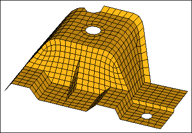
| 5. | Observe the red, 1D elements (free edges), and try to identify gaps in the continuity of the mesh. |
| Tip: | Look closely at the free edges interior to the model. |
| 6. | In the Model browser, Component folder, click  next to shells to turn off its element display. next to shells to turn off its element display. |
| 7. | Continue to identify which red, free edges do not belong in the model. |
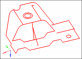
All of the red, free edges in the model
|
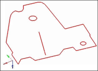
Red, free edges that belong in the model
|
| 8. | Turn the element display back on for the shells component. |
Step 3: Correct the shell element connectivity problems using the Edges panel.
| 1. | In the tolerance= field, enter 0.01. |
| 2. | In the graphics area, select any element. HyperMesh selects the component containing the element you selected. |
| 3. | Click preview equiv. HyperMesh creates a sphere ( ) on the nodes that have a distance between each other that is equal to or less than the specified tolerance. ) on the nodes that have a distance between each other that is equal to or less than the specified tolerance. |
| Note: | The Status bar reads, "81 nodes were found." A sphere was not created on every node along all of the red, free edges. To identify the rest of the nodes, you must specify a larger tolerance. |
| 4. | In the tolerance = field, increase the value until you have identified all 96 nodes. |
| Note: | Do not increase the tolerance too much. Although you will identify the 96 nodes, an excessively large tolerance value may collapse elements when the identified nodes are equivalenced. |
| Tip: | Find the maximum tolerance value that you can safely use without collapsing the elements by pressing F10 to go to the Check Elems panel, 2d subpanel, and clicking length. The Status bar reads "… The min length is 1.49." This message indicates that you can safely use a tolerance value < 1.49, without causing any elements to collapse when identified nodes are equivalenced. Return to the Edges panel by clicking return. |
The nodes identified with preview equivalence
| 5. | Click equivalence. HyperMesh equivalenced 96 coincident nodes. |
| 6. | Rotate and observe the model to see that the mesh still looks as it should, and that none of the elements are collapsed. |
| 7. | Click delete edges. HyperMesh deletes the red, free edges and their component, ^edges. |
Step 4: Review the model’s free edges again to confirm that all of the shell element connectivity problems have been corrected.
In this step, you should still be in the Edges panel.
| 1. | Click find edges. HyperMesh creates a red, 1D element along each shell element edge that is free. |
| 2. | Observe the red, 1D elements (free edges). Are there any red, free edges that should not belong if the mesh was continuous, or if all of the elements were connected? |
| Note: | Red, free edges should only exist on the perimeter of the part and on the periphery of the internal holes. |
| 3. | In the Model browser, turn off the element display of the shells component. |
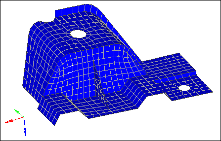
| 4. | Verify that all of the free, red edges belong in the model. |
Red, free edges that belong in the model
| 6. | Turn the element display back on for the shells component. |
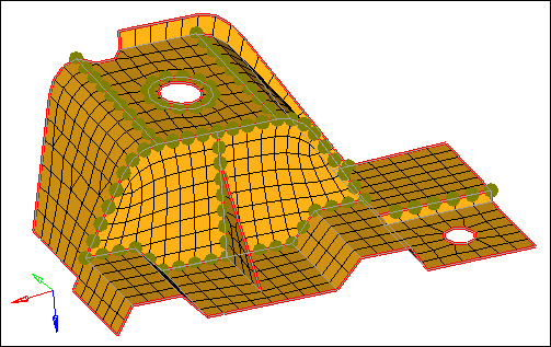
Step 5: Display the element normals and adjust them to point in the same direction.
| 1. | To open the Normals panel, do one of the following: |
| • | From the menu bar, click Mesh > Check > Elements > Normals. |
| • | On the Checks toolbar, click  (Normals). (Normals). |
| • | From the main menu, go to the Tool page, then click normals. |
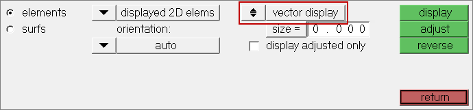
| 2. | Go to the elements subpanel. |
| 3. | Set the toggle to vector display. |
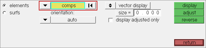
| 4. | Set the top switch to comps. |
| 5. | In the graphics area, select any element. HyperMesh selects the component containing the element you selected. |
| 6. | Click display. HyperMesh draws vectors from the element centroids, which indicate the direction of the element normals. |
| Note: | The arrows do not all point from the same side of the part. For some analyses, the element normals should point from the same side. |
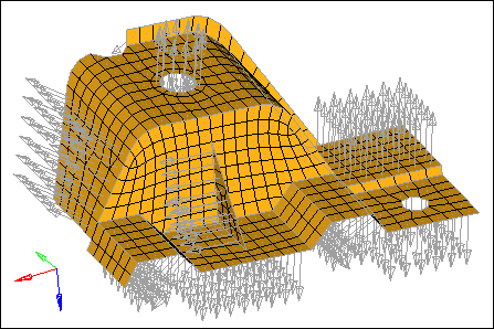
| 7. | In the size = field, enter the size which the normal should be in model units. |
| Note: | When size = is set to 0, the vector will be 10% of the screen. |
| 9. | Toggle vector display to color display. |
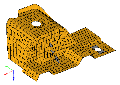
| 10. | Click display. HyperMesh displays, on each side of the part, the element normals using the colors red and blue. |
| Note: | The red side of the elements is the positive normal direction, while the blue side is the negative normal direction. |
| 11. | Under orientation, set the switch to elem. |
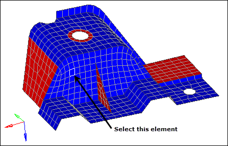
| 12. | In the graphics area, select an element as indicated in the following image. |
| 13. | Click adjust. All of the elements on both sides of the part are the same color, red or blue. |
| Note: | The Status bar reads: "[X] elements have been adjusted." |
| 14. | Optional: If after adjusting the normals there are still elements on one side of the part which are of different color, set the switch to elem under Orientation, select the elements that are of a different color, and then click reverse. |
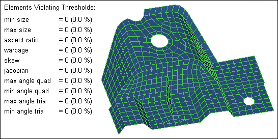
Step 6: Review the quality of the elements using the check elems panel.
| 1. | To open the Check Elems panel, do one of the following: |
| • | From the menu bar, click Mesh > Check > Elements > Check Elements. |
| • | On the Checks toolbar, click  (Check Elements). (Check Elements). |
| • | From the main menu, go to the Tool page, then click check elems. |
| 2. | Go to the 2-d subpanel. |
| 3. | Verify that the jacobian < field is set to 0.7. |
| 4. | Click jacobian. HyperMesh highlights the elements that have a jacobian of less than 0.7, and the Status bar displays a message indicating how many elements failed this check. |
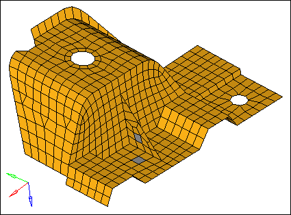
| Note: | There are several elements on the triangular rib and around the smaller of the two holes that have a jacobian of less than 0.7. |
| 5. | In the graphics area, click an element. A window appears that lists each quality check result for the element. |
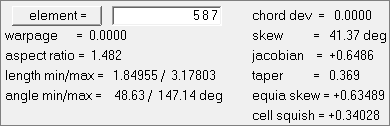
| 6. | Close the pop-up window by right-clicking. |
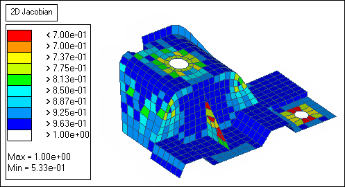
| 7. | On the right side of the panel, switch from standard to assign plot. |
| 8. | Click jacobian. A legend for jacobian values appears and each element is colored accordingly. |
| Note: | The red elements have a jacobian less than the threshold, 0.7. |
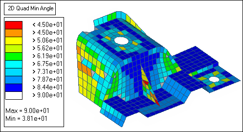
| 9. | Under quads, verify that the min angle < is set to 45. |
| 10. | Click min angle to determine if any quad elements have an angle of less than 45. |
| Note: | A couple of the elements on the rib have an angle of less than 45. |
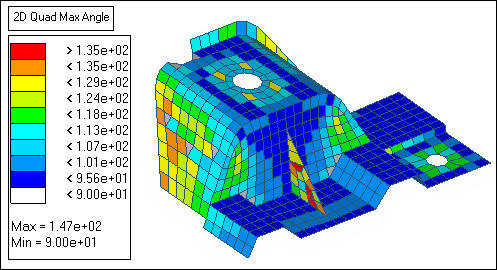
| 11. | Under quads, verify that the max angle > field is set to 135. |
| Note: | Several elements on the rib have an angle greater than 135. |
Step 7: Remesh the elements on the rib using the Automesh panel.
| 1. | To open the Automesh panel, do one of the following: |
| • | From the menu bar, click Mesh > Create > 2D AutoMesh. |
| • | From the main menu, go to the 2D page and click automesh. |
| 2. | Go to the size and bias subpanel. |
| 3. | Set the entity selector to elems. |
| 4. | At the bottom of the panel, set the toggle to interactive. |
| 5. | In the element size= field, enter 3.5. |
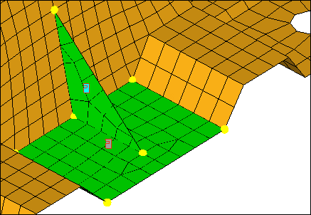
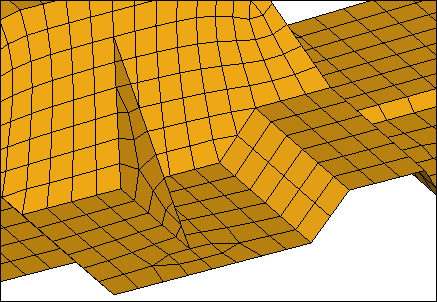
| 6. | In the graphics area, select one rib element as indicated in the following image. |
| 7. | Select one element on the plane of elements perpendicular to the rib and in the same plane as the rib’s shortest edge as indicated in the following image.. |
Example of elements to select
| 8. | Complete your selection of elements by clicking elems >> by face. |
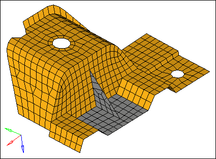
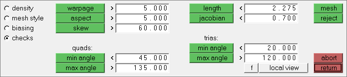
Elements selected using by face
| 9. | Click mesh. The meshing module opens. |
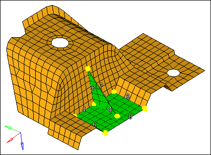
| 10. | In the density subpanel, left-click on the rib’s hypotenuse edge density number to increase it to 9 as indicated in the following image. |
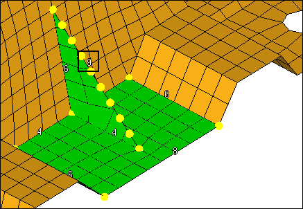
| 11. | Left-click on the rib’s shortest edge density number to increase it to 5 as indicated in the following image. |

| 12. | Keep all of the other element edge densities the same. |
| 13. | Go to the mesh style subpanel. |
| 14. | Under mesh method, set the last option to free (unmapped). |
| 15. | Under mesh method, click set all. |
| 16. | Preview the mesh by clicking mesh. |
| 17. | Go to the checks subpanel. |
| 18. | Check the jacobian, quads: min angle, and quads: max angle. |
| Note: | None of the elements failed the minimum and maximum angle checks, and only a couple of the elements have a jacobian of less than 0.7. The smallest jacobian is 0.68, which can still be considered good quality. |
| 19. | Accept the mesh and return to the main menu by clicking return. |
Step 8: Use the Smooth panel to adjust the node placement on the rectangular plane of the remeshed elements.
| 1. | Open the Smooth panel by clicking Mesh > Cleanup Elements > Smooth. |
| 2. | Go to the plates subpanel. |
| 3. | Activate the smooth: elems selector. |
| 4. | Select an element on the rectangular plane of the remeshed elements. |
| 5. | Click elems >> by face. |
| 6. | In the iterations= field, enter 10. |
| 7. | Switch the smoothing algorithm from autodecide to shape corrected. |
Step 9: Remove tria elements from another area of the model using the edit element panel, split and combine subpanels.
| 3. | Go to the split subpanel. |
| 4. | Verify that the splitting line: points selector is active. |
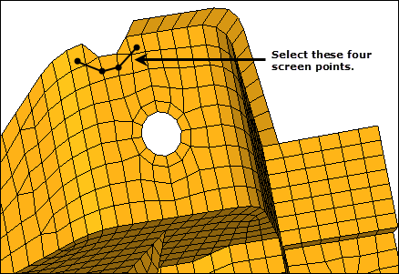
| 5. | Click the four screen points as indicated in the following image. HyperMesh draws temporary line segments to connect the points. |
| Tip: | Right-click to undo the last line segment drawn, or click delete line to start over and reselect points. |
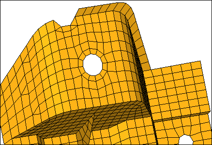
| 6. | Click split. HyperMesh splits the elements that have a line passing through them. |
| Note: | The resulting mesh should look like the mesh in the following image, with two pairs of adjacent tria elements. |
| 7. | Go to the combine subpanel. |
| 8. | Set the toggle to combine to quad. |
| 9. | Select the two adjacent tria elements as indicated in the following image. |
| 10. | Click combine. HyperMesh combines the two tria elements into one quad element. |
| 11. | Repeat 11.9 and 11.10 to combine the other two tria elements into one quad element. |
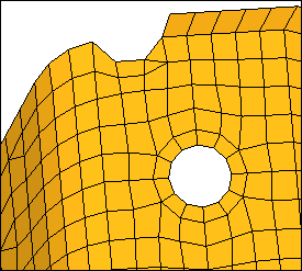
Step 10: Modify washer radius and optimize element quality by using Cleanup tools.
| 1. | From the 2D page, click qualityindex. |
| 3. | Click modify hole & washers. |
| 4. | Clear the edit checkbox. |
| 5. | Select a node on the washer as indicated in the following image. The radius field displays a value of 5.98. |
| 6. | Select the edit check box. |
| 7. | In the radius field, enter 7. |
| 8. | Select the link washers checkbox. |
| 9. | Select the remesh number of layers checkbox, and then enter 3 in the editable field. |
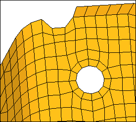
| 10. | Select a node on the washer as indicated in the previous image. HyperMesh changes the washer's radius to 7. |
| Note: | Because you selected the link washers checkbox, the hole's radius will change accordingly (approx. 4.68). Due to the change in the hole's and washer's dimensions, elements around the washer will be distorted and will fail in quality. You can correct all of the failed elements in the model using the node optimize and element optimize cleanup tools. |
| 12. | Select a few nodes on the elements that you modified in step 9. When you select a node, HyperMesh repositions it so that the elements attached to the node will have the best possible quality based on the criteria specified in the Quality Index panel. |
| 13. | Click element optimize. |
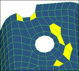
| 14. | Select the red and yellow elements in the model. When you select an element, HyperMesh adjusts it to have the best quality possible based on the criteria specified in the Quality Index panel. |
| Note: | If you select a red element, it may turn yellow or it may no longer have a color assigned. If you select a yellow element, it may no longer have a color assigned. |
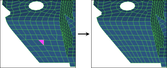
| 15. | Click drag tria element. |
| Note: | Use the drag tria element tool to drag a tria element toward a different location in the model, or out of the model completely. |
| 16. | Left-click on a tria element and drag it toward the bottom edge of the model until it is out of the model completely. HyperMesh highlights the selected tria element in pink. |
Step 11: Add a ring of radial elements around the smaller of the two holes.
| 1. | Open the Utility tab by clicking View > Browsers > HyperMesh > Utility from the menu bar. |
| 4. | In the Add Washer along Circular Holes dialog, double-click Nodes. |
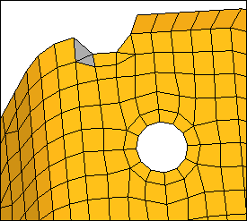
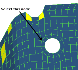
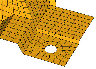
| 5. | Select one of the nodes on the edge of the smaller hole as indicated in the following image. |
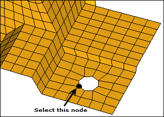
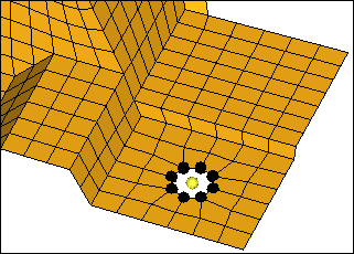
| 6. | Click proceed. HyperMesh selects nodes around the hole. |
| 7. | Under Selection, set the toggle to Width. |
| 8. | Under Value, enter 3.0. |
| 9. | Select the Minimum number of nodes around the hole checkbox. |
| 10. | In the Density field, enter 12. |
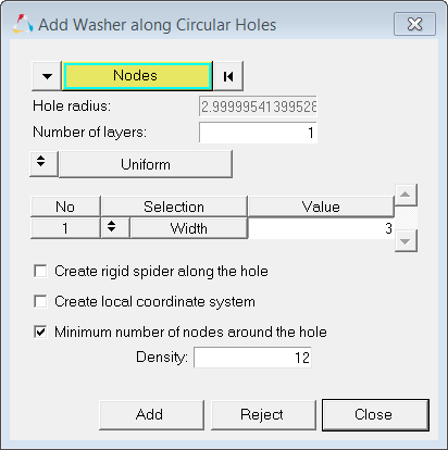
Settings in the Add Washer along Circular Holes dialog
| 11. | Click Add. HyperMesh creates a washer around the hole. |
Step 12: Imprint Mesh to different destinations.
| 1. | In the Model browser, Component folder, right-click on IMPRINT1 and select Show from the context menu. |
| 4. | Go to the imprint subpanel. |
| Note: | Use the imprint subpanel to sync or line up different, overlapping component's meshes in order to facilitate a better connection modeling between the components. |
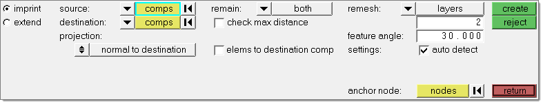
| 5. | Verify that the source selector is set to comps, and then select the IMPRINT1 component. |
| 6. | Verify that the destination selector is set to comps, and then select the shells component. |
| 7. | From the remain drop-down list, select destination. |
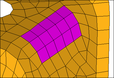
| Note: | This option takes existing elements/components that can be imprinted into destination elements/components, and changes their direction and destination. |
Original: Violet elements are offset from yellow.
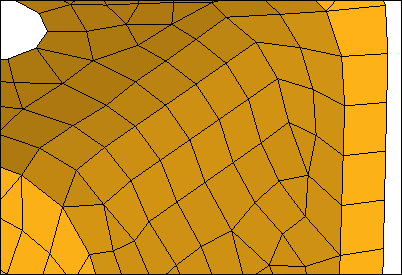
| 8. | Clear the elems to destination comp checkbox. |
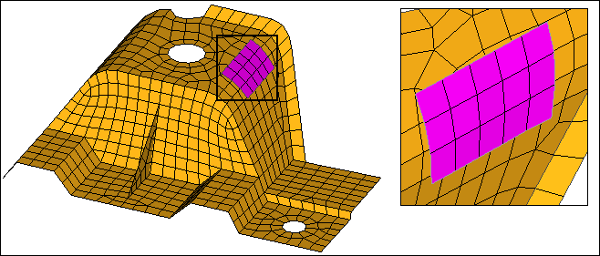
Violet source elements are imprinted in destination (yellow).
| 11. | Repeat steps 12.5 and 12.6 to select the IMPRINT1 component as the source and the shells component as the destination. |
| 12. | From the remain drop-down list, select destination. |
| 13. | Select the elems to destination comp check box. |
Violet source elements are imprinted in destination (yellow), element organized into yellow component.
| 15. | Repeat steps 12.5 and 12.6 to select the IMPRINT1 component as the source and the shells component as the destination. |
| 16. | From the remain drop-down list, select source. |
| 17. | Select the elems to destination comp checkbox. |
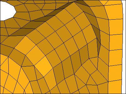
Yellow destination elements are imprinted to Violet elements, and elements are organized into the yellow component.
Step 13: Extend Mesh to different destinations.
| 1. | In the Model browser, Component folder, right-click on IMPRINT1 and select Hide from the context menu. |
| 2. | Right-click on the EXTEND component and select Show from the context menu. |
| 3. | From the 2D page, click mesh edit. |
| 4. | Go to the extend subpanel. |
| Note: | Use the extend subpanel to create smoothly-meshed connections between different components that do not quite touch, but are meant to. Mesh can be imprinted such that both components are remeshed to match, or the source component is remeshed to match the destination component, and vice-versa. In addition, you can merge the elements of the source component into the destination component. |
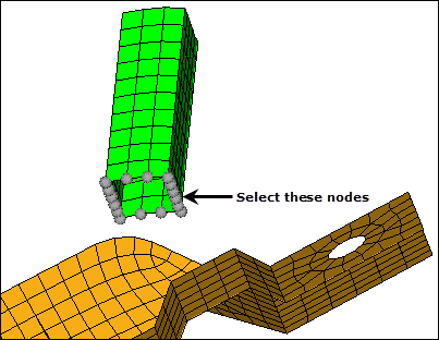
| 5. | Click source: nodes >> by path. |
| 6. | On the EXTEND component, select the source nodes indicated in the following image. |
| 7. | Verify that the destination selector is set to comps, and then select the shells component. |
| 8. | From the projection list, select along vector. |
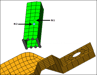
| 9. | Activate the N1 selector. |
| 10. | Select N1 and N2, as indicated in the following image, to define the direction. |
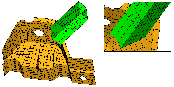
| 11. | Clear the remesh extension checkbox. |
| 12. | Click create. HyperMesh connects the two parts with one element along the projection, because the remesh extension checkbox was clear. |
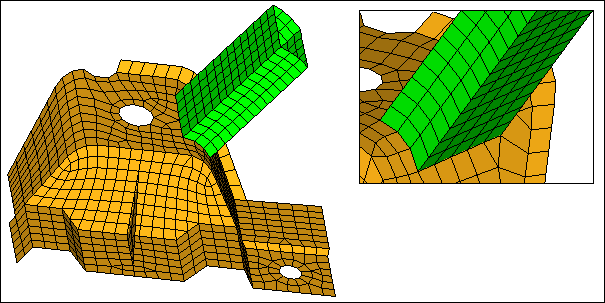
| 14. | Repeat step 13.5 and 13.11, but select the remesh extension checkbox. |
| 15. | Click create. HyperMesh connects the two parts with remeshed elements along the projection, because the remesh extension option was selected. |
Step 14 (Optional): Save your work.
With this exercise completed, you can save the model if desired.
| 1. | From the menu bar, click File > Save > Model. |
See Also:
HyperMesh Tutorials


