In this tutorial, you will learn how to:
| • | Create constraints (OPTISTRUCT SPC) on the channel’s geometry lines |
| • | Create a force (OPTISTRUCT FORCE) on the bracket to simulate a pressing load on it |
| • | Define a load step (OPTISTRUCT SUBCASE) |
| • | Export the model to an OptiStruct input file |
| • | Submit the OptiStruct input file to OptiStruct |
| • | Review the resulting HTML report file |
The purpose of using a finite element (FE) pre-processor is to create a model, which can be run by a solver. A finite element solver can solve for responses of parts to loading conditions on them. The loads can be in the form of boundary constraints, forces, pressures, temperatures, and so on.
In this tutorial, you will gain an understanding of the basic concepts for creating a solver input file by using a template. More specifically, you will learn how to define loading conditions on a model, specify solver specific controls, and submit an input file to a solver from HyperMesh.
Model Files
This exercise uses the channel_brkt_assem_loading.hm file, which can be found in the hm.zip file. Copy the file(s) from this directory to your working directory.
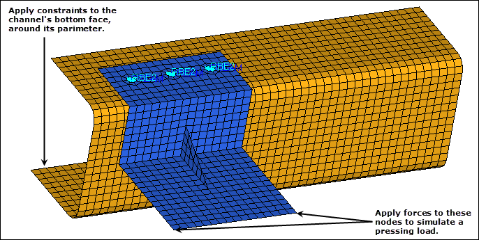
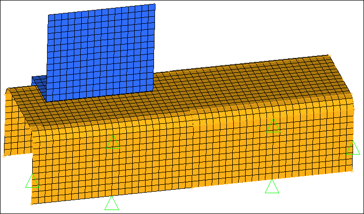
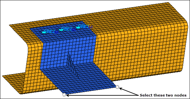
The model contains the bracket and channel assembly in the following image.
Exercise: Setting up Loading Conditions
Step 1: Load the OptiStruct user profile.
| 1. | Start HyperMesh Desktop. |
| 2. | In the User Profile dialog, select OptiStruct. |
Step 2: Retrieve and view the HyperMesh model file, channel_brkt_assem_loading.hm.
| 1. | Open a model file by clicking File > Open > Model from the menu bar, or clicking  on the Standard toolbar. on the Standard toolbar. |
| 2. | In the Open Model dialog, open the channel_brkt_assem_loading.hm file. A model appears in the graphics area. |
Step 3: Create two load collectors named pressing_load and constraints.
| 1. | In the Model browser, right-click and select Create > Load Collector from the context menu. HyperMesh creates and opens a load collector in the Entity Editor. |
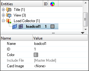
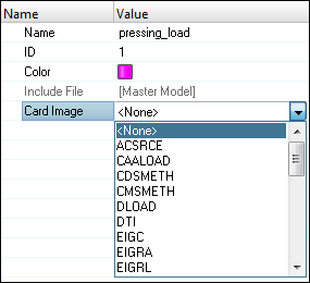
| • | For Name, enter pressing_load. |
| • | Click the Color icon, and select a color for the load collector. |
| • | Set Card Image to <None>. |
| 3. | Repeat steps 3.1 and 3.2 to create second load collector labeled constraints. |
Step 4: Apply constraints (OPTISTRUCT SPC) to the channel’s line geometry.
| 1. | In the Model browser, View folder, right-click on View2 and select Show from the context menu. |
| Note: | By selecting this view, HyperMesh sets the component's and load collector's displays back to what they were when the view was saved. The load collectors that you created in step 3 are now turned off because they did not exist when the view was saved. You will need to turn these back on to see the display of the BCs when you create them in the next steps. |
| 2. | In the Load Collector folder, click  next to pressing_load and constraints to turn on the display of their geometry. next to pressing_load and constraints to turn on the display of their geometry. |
| 3. | In the Component folder, click next to channel to turn on the display of its geometry. |
| 4. | Open the Constraints panel by clicking BCs > Create > Constraints from the menu bar. |
| 5. | Go to the create subpanel. |
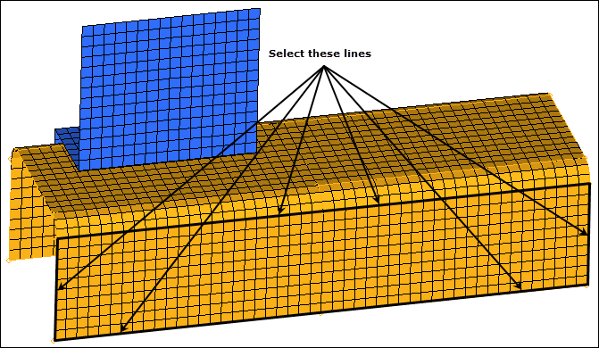
| 6. | Set the entity selector to lines. |
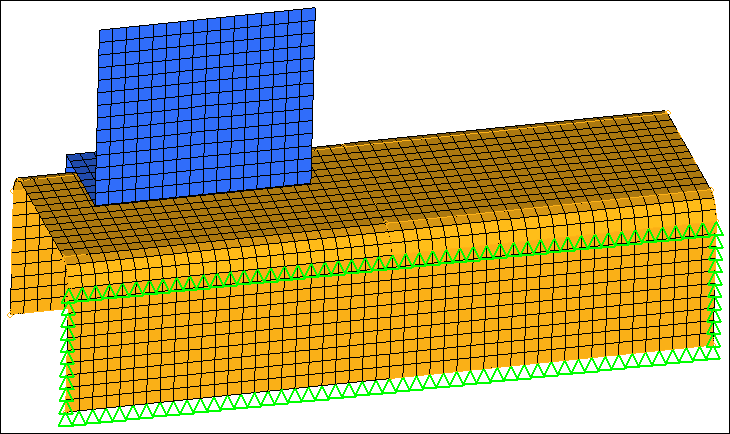
| 7. | Select the six lines on the perimeter of the channel’s bottom surface as indicated in the following image. |
| 8. | Verify that all six dofs (degrees of freedom) are selected. |
| Note: | For an OptiStruct linear static analysis, dof 1, 2, and 3 represent translations in the global x-, y-, and z-directions, respectively. Dof 4, 5, and 6 represent rotations about the global x-, y- and z-axis, respectively. |
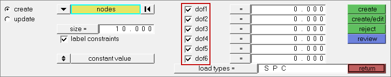
| 9. | Click load types = and select SPC. |
| 10. | Click create. Hypermesh creates constraints on the lines. |
| 11. | In the size = field, enter 5. HyperMesh reduces the display size of the constraints. |
| 12. | Select the label constraints checkbox. HyperMesh displays a label for each constraint. |
| Note: | The labels identify what dofs are assigned to the constraints. |
| 13. | Exit the main menu by clicking return. |
Step 5: Map the constraints (OPTISTRUCT SPC) on the geometry lines to the channel nodes associated to the lines.
| 1. | Open the loads on geometry panel by clicking BCs > Loads on Geometry from the menu bar. |
| 3. | Select the load collector, constraints. |
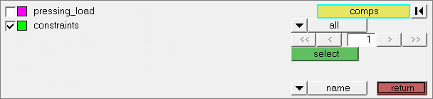
| 5. | Click map loads. HyperMesh creates a constraint at each node associated to the geometry lines. |
| 7. | In the Model browser, Component folder, turn off the display of geometry for all component collectors. |
Step 6: Prepare to create forces (OPTISTRUCT FORCE) on the bracket for the pressing load case.
| 1. | In the Model browser, View folder, right-click on View3 and select Show from the context menu. |
| 2. | In the Load Collector folder, right-click on pressing_load and select Make Current from the context menu. |
| Note: | The pressing_load load collector is now the current load collector, and any loads created will be placed in this collector. |
| 3. | Right-click on pressing_load and select Show from the context menu. |
Step 7: Create two forces (OPTISTRUCT FORCE) on the bracket for the pressing load case.
| 1. | Open the forces panel by clicking BCs > Create > Forces from the menu bar. |
| 2. | Go to the create subpanel. |
| 3. | Set the entity selector to nodes. |
| 4. | Select the two nodes indicated in the following image. |
| 5. | In the magnitude = field, enter 5. |
| 6. | Set the orientation selector to y-axis. |
| 7. | Click load types = and select FORCE. |
| 8. | Click create. HyperMesh creates two forces. |
| 9. | In the magnitude % = field, enter 200.0. HyperMesh increases the display size of the forces. |
| 10. | Select the label loads checkbox. Each force displays the label FORCE = 5.00e+00. |
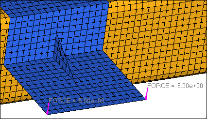
The two forces created for the pressing load case
Step 8: Define the load step for the pressing load case.
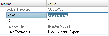
| 1. | Create a Load Step by right-clicking in the Model browser and selecting Create > Load Step from the context menu. HyperMesh creates and opens a load step in the Entity Editor. |
| • | For Name, enter pressing_step. |
| • | Set Analysis type to Linear Static. |
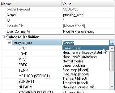
| • | For SPC, click Unspecified >> Loadcol. |
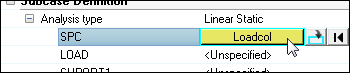
| • | In the Select Loadcol dialog, select constraints and then click OK. |
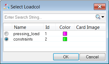
| • | For LOAD, click Unspecified >> Loadcol. |
| • | In the Select Loadcol dialog, select pressing_load and then click OK. |
Step 9: Display and mask the load step (the load collectors defined in the load step).
| 1. | In the Model browser, Load Step folder, right-click on pressing_step and select Hide from the context menu. HyperMesh hides the pressing_load and constraints load collector |
| 2. | Right-click on pressing_step again and select Show from the context menu. |
See Also:
HyperMesh Tutorials


