In this tutorial, you will learn how to:
| • | Create a solver input file by using a template |
| • | Review entities in HyperMesh to see how they will appear in the solver input file |
| • | Define materials and properties |
| • | Select solver element types for HyperMesh element configurations |
The purpose of using a finite element (FE) pre-processor is to create a model that can be run by a solver. HyperMesh interfaces with many FE solvers and all of them have unique input file formats. HyperMesh has a unique template(s) for each solver it supports. A template contains solver specific formatting instructions, which HyperMesh uses to create an input file for that solver.
Model Files
This exercise uses the channel_brkt_assem_analysis.hm file, which can be found in the hm.zip file. Copy the file(s) from this directory to your working directory.
The model contains the bracket and channel assembly in the following image.
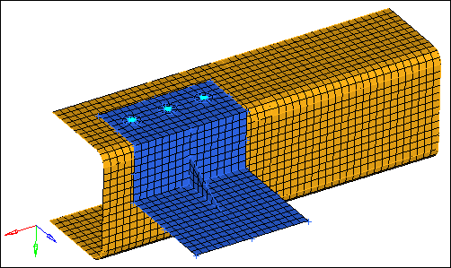
Exercise: OptiStruct Linear Statics Setup for a Shell Assembly
Step 1: Load the OptiStruct user profile.
| 1. | Start HyperMesh Desktop. |
| 2. | In the User Profile dialog, select OptiStruct. |
Step 2: Retrieve and view the file, channel_brkt_assem_analysis.hm.
| 1. | Open a model file by clicking File > Open > Model from the menu bar, or clicking  on the Standard toolbar. on the Standard toolbar. |
| 2. | In the Open Model dialog, open the channel_brkt_assem_analysis.hm file. A model appears in the graphics area. |
Step 3: Review a bracket element to identify what type of OptiStruct element it is and to see how it will be formatted in the OptiStruct input file.
| 1. | Open the Card Edit panel by clicking  on the Collectors toolbar. on the Collectors toolbar. |
| 2. | Set the entity selector to elems. |
| 3. | In the graphics area, select an element on the bracket component. |
| Note: | The bracket component is blue. |
| 4. | Click edit. The Card Image opens, and indicates that the selected element is an OptiStruct CQUAD4 or CTRIA3, depending on whether you selected a quad or tria element. |
| Note: | EID is the element’s ID, PID is the ID of the element’s property, and G(X) is the grid (node) ID that makes up the element. Options specific to the CQUAD4 or CTRIA3 appear in the menu panel area. |
| 5. | Close the Card Image by clicking return. |
| 6. | Exit the Card Edit panel by clicking return. |
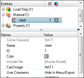
Step 4: Review and edit the existing steel material’s card image by accessing the card editor from the Model browser.
This material is defined for the channel.
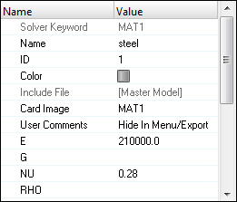
| 1. | In the Model browser, Material folder, click steel. The Entity Editor opens and displays the material's corresponding data. |
| Note: | The card image indicates the material is of OptiStruct type MAT1. |
| 2. | In the Entity Editor, NU (Poisson's Ratio) field, change the value from 0.3 to 0.28. |
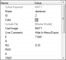
Step 5: Define a material collector named aluminum for the bracket.
This material is defined for the channel.
| 1. | In the Model browser, right-click and select Create > Material from the context menu. HyperMesh creates and opens a material in the Entity Editor. |
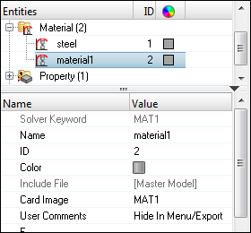
| 2. | For Name, enter aluminum. |
| 3. | Set Card Image to MAT1. |
| 4. | For E (Young's Modulus), enter 7.0e4. |
| 5. | For NU (Poisson's Ratio), enter 0.33. |
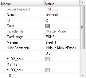
Step 6: Define a property collector (PSHELL card image) that will be assigned to the channel component collector.
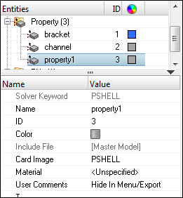
| 1. | In the Model browser, right-click and select Create > Property from the context menu. HyperMesh creates and opens a property in the Entity Editor. |
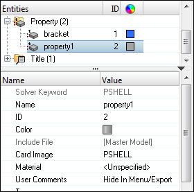
| 2. | For Name, enter channel. |
| 3. | Set Card Image to PSHELL. |
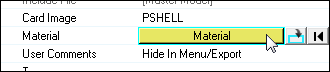
| 4. | For Material, click Unspecified >> Material. |
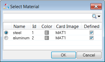
| 5. | In the Select Material dialog, select steel and then click OK. HyperMesh assigns the material. |
| 6. | For T (thickness), enter 3.0. |
Step 7: Assign the channel property to the channel component.
| 1. | In the Model browser, Component folder, click channel. The Entity Editor opens and displays the component's corresponding data. |
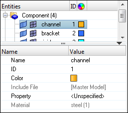
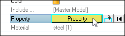
| 2. | For Property, click Unspecified >> Property. |
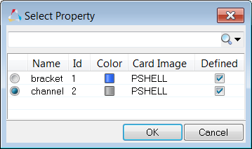
| 3. | In the Select Property dialog, select channel and then click OK. HyperMesh assigns the property channel to the component channel. |
Step 8: Update the bracket property to have a PSHELL card image, a thickness of 2.0, and the aluminum material.
| 1. | In the Model browser, Property folder, click bracket. The Entity Editor opens and displays the properties' corresponding data. |
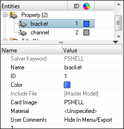
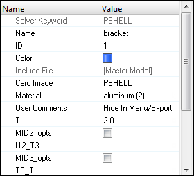
| 2. | Set Card Image to PSHELL. |
| 3. | For Material, click Unspecified >> Material. |
| 4. | In the Select Material dialog, select aluminum and then click OK. HyperMesh assigns the material aluminum to the property bracket. |
| 5. | For T (thickness), enter 2.0. |
Step 9: Calculate the section properties for the bar elements (OptiStruct CBEAM) by using HyperBeam.
| 1. | Open the HyperBeam panel by clicking Properties > HyperBeam from the menu bar. |
| 2. | Go to the standard section subpanel. |
| 3. | Set the standard section library to HYPERBEAM. |
| 4. | Set the standard section type to solid circle. |
| 5. | Click create. HyperMesh invokes the HyperBeam module. |
| Note: | The solid, green circle represents the cross section. Under the local coordinate system you should see the number, 10.0000, which is the circle’s radius. |
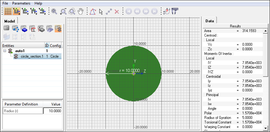
HyperBeam module with the standard solid circle section
| 6. | Under Parameter Definition, click the Value field next to Radius (r) and change the value from 10 to 3. HyperMesh updates the values in the Data pane to reflect the circle's new diameter. |
| 7. | In the Model browser, right-click on circle_section.1 and select Rename from the context menu. |
| 8. | In the editable field, rename the section 6mm_Beam_Sect. |
| 9. | Close the HyperBeam module and return to your HyperMesh session by clicking File > Exit from the menu bar. |
| 10. | Return to the main menu by clicking return. |
Step 10: Create a property collector named bars_prop for the bar elements (OptiStruct).
| 1. | In the Model browser, right-click and select Create > Property from the context menu. HyperMesh creates and opens a property in the Entity Editor. |
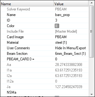
| 2. | For Name, enter bars_prop. |
| 3. | Set Card Image to PBEAM. |
| 4. | For Material, click Unspecified >> Material. |
| 5. | In the Select Material dialog, select steel and then click OK. HyperMesh assigns the material steel to the property bars_prop. |
| 6. | For Beam Section, click Unspecified >> Beamsection. |
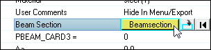
| 7. | In the Select Beam Section dialog, select 6mm_Beam_Sect and then click OK. HyperMesh assigns the beam section, and populates the parameter fields in the PBEAM card with the data in the 6mm_Beam_Sect beam section. |
Step 11: Update the CBEAM elements in the bolts component to use the PBEAM Property.
| 1. | In the Model browser, Component folder, click bolts. The Entity Editor opens and displays the component's corresponding data. |
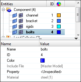
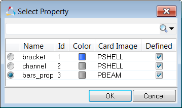
| 2. | For Property, click Unspecified >> Property. |
| 3. | In the Select Property dialog, select bars_prop and then click OK. HyperMesh assigns the property bars_prop to the component bolts. |
Step 12: Define a H3D file to be output from OptiStruct by using the control cards panel.
| 1. | Open the Control Cards panel by clicking Setup > Create > Control Cards from the menu bar. |
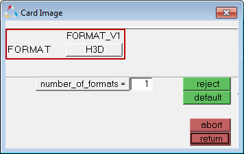
| 2. | In the Card Image, select the control card FORMAT. |
| Note: | In the card image, the FORMAT line is set to H3D. This specifies OptiStruct to output results to a Hyper3D (H3D) file, which can be viewed in the HyperView Player. A HTML report file will be output and the H3D file will be embedded in it. |
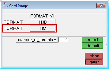
| 3. | In the number_of_formats = field, enter 2. A second FORMAT line appears in the card image. |
| 4. | In the second FORMAT line, click H3D and then select HM. |
| Note: | This option specifies OptiStruct to output the results to a HyperMesh binary results file, allowing the results to be post-processed within HyperMesh. |
| 5. | Exit to the Control Cards panel by clicking return. |
| Note: | The FORMAT button is now green, which indicates that the card will be exported to the OptiStruct input file. |
| 6. | Return to the main menu by clicking return. |
Step 13: Export the model to an OptiStruct input file.
| 1. | From the menu bar, click File > Export > Solver Deck. |
| 2. | In the File field, click  . . |
| 3. | In the Select OptiStruct file dialog, navigate to your working directory and save the file as channel_brkt_assem_loading.fem. |
| 4. | Click Export. HyperMesh exports the model as an OptiStruct .fem input file for the solver specified by the current user profile. |
Step 14: Review the contents of the file channel_brkt_assem_loading.fem.
| 1. | In any text editor (Notepad, Wordpad, Vi, etc.), open the file channel_brkt_assem_loading.fem. |
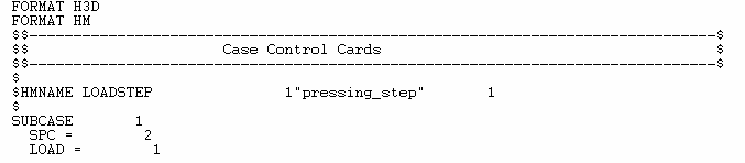
| 2. | Near the top of the file, note the following: |
| • | The line FORMAT HM, which you specified in HyperMesh |
| • | The load step (OptiStruct SUBCASE) named pressing_step which you defined in HyperMesh |
| • | Under the load step, the load collector ids (OptiStruct load and constraint set identification numbers) |
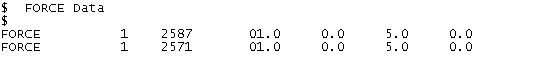
| 4. | Note the load set identification number for each force (OptiStruct FORCE). It is either 1 or 2 as shown below. These numbers correspond to the numbers under the load steps in the file. |
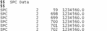
| 5. | Search for "SPC" (HyperMesh constraint). |
| 6. | Note the constraint set identification number for each constraint (OptiStruct SPC). It is 2 as shown below, which lists a few of the constraints. This number corresponds to the number under the load steps in the file. |
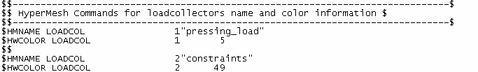
| 7. | Search for the load collector name "pressing_load." |
| 8. | Note the load collectors, pressing_load and constraints. Also, note their collector ID and color ID. When the model is imported into HyperMesh, the loads are organized into these load collectors and have these IDs and colors. |
| 9. | Close the file channel_brkt_assem_loading.fem. |
Step 15 (Optional): Save your work.
With the exercise completed, you can save the model as a HyperMesh file, if desired.
See Also:
HyperMesh Tutorials


