In this tutorial, you will learn how to assign element material orientation using the following:
Model Files
This exercise uses the composites.hm file, which can be found in the hm.zip file. Copy the file(s) from this directory to your working directory.
Step 1: Load the OptiStruct user profile.
| 1. | Start HyperMesh Desktop. |
| 2. | In the User Profile dialog, select OptiStruct. |
Step 2: Retrieve and view the file, composites.hm.
| 1. | Open a model file by clicking File > Open > Model from the menu bar, or clicking  on the Standard toolbar. on the Standard toolbar. |
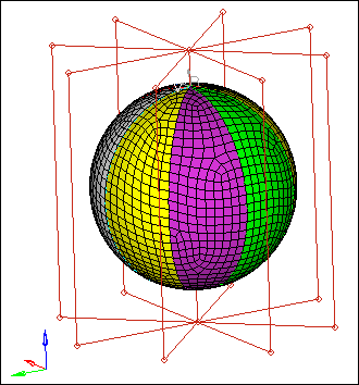
| 2. | In the Open Model dialog, open the composites.hm file. A model appears in the graphics area. |
Step 3: Update all of the elements to the correct element types for OptiStruct.
| 1. | Open the Element Type panel by clicking Mesh > Assign > Element Type from the menu bar. |
| 2. | Click elems >> all. HyperMesh selects all of the element types (1D, 2D, and 3D). |
| 4. | Return to the main menu by clicking return. |
Step 4: Assign element material coordinate direction using system ID.
| 1. | Open the Composites panel by clicking composites from the 2D page. |
| 2. | Go to the material orientation subpanel. |
| 3. | Set the entity selector to elems. |
| 5. | Set the Material orientation method to by system ID. |
| 6. | Activate the system selector. |
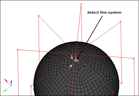
| 7. | Select the rectangular system on top of ball as indicated in the following image. |
| 8. | Click color and select a display color for the review vectors or lines. |
| 9. | In the size = field, enter 2.0. |
| Note: | This value specifies, in model units, how large the review vectors are when displayed. |
| 11. | Open the Card Edit panel by clicking  on the Collectors toolbar. on the Collectors toolbar. |
| 12. | Set the entity selector to elems. |
| 13. | Select any element in the model. |
| 15. | In the Card Previewer dialog, review the card. |
| Note: | This function assigns the ID of the coordinate system to the selected elements. This can be verified by reviewing the MCID field of the CQUAD4 card populated with System ID 1 for the currently loaded OptiStruct user profile. How each analysis code interprets this information varies. For OptiStruct, refer to the CQUAD4 and PCOMP(G) bulk data cards in the Bulk Data Section of the OptiStruct Reference Manual. For visualization purposes HyperMesh also projects the x-axis of the selected coordinate system onto the face of the shell elements to define the x-axis of the material coordinate system. If you later modify the system, the element material coordinate directions change implicitly. |
| 16. | Exit the Card Previewer by clicking return. |
| 17. | Exit the Card Edit panel and return to the Composites panel by clicking return. |
Step 5: Assign element material coordinate direction using a system axis.
In this step you should be in the Composites panel, material orientation subpanel.
| 1. | Set the entity selector to elems. |
| 3. | Set the Material orientation method to by system axis. |
| 4. | Activate the system selector. |
| 5. | Select the rectangular system on top of ball as indicated in the following image. |
| 6. | Under the system selector, set the switch to local 2-axis. |
| 7. | In the size= field, enter 2.0. |
| Note: | This value specifies, in model units, how large the review vectors are when displayed. |
| 8. | Click color and select a display color for the review vectors or lines. |
| 10. | Open the Card Edit panel. |
| 11. | Set the entity selector to elems. |
| 12. | Select any element in the model. |
| 14. | In the Card Previewer dialog, review the card. |
| Note: | This function assigns a material angle to the selected elements, which for OptiStruct is defined as the angle between the vector direction connecting node1 and node2 of the shell element (that is, the element coordinate system x-axis) and the projection of the selected local axis onto the surface of the shell element. This can be verified by reviewing the THETA field of the CQUAD4 card populated with an angle (in degrees) for the currently loaded OptiStruct user profile. Each element in this case will have a unique THETA value as defined by the projection. How each analysis code interprets this information varies. For OptiStruct, refer to the CQUAD4 and PCOMP(G) bulk data cards in the Bulk Data Section of the OptiStruct Reference Manual. For visualization purposes HyperMesh also projects the local axis of the selected coordinate system onto the face of the shell elements to define the x-axis of the material coordinate system. |
| 15. | Exit the Card Previewer. |
| 16. | Exit the Card Edit panel and return to the Composites panel. |
Step 6: Assign element material coordinate direction using a vector.
In this step you should be in the Composites panel, material orientation subpanel.
| 1. | Set the entity selector to elems. |
| 3. | Set the Material orientation method to by vector. |
| 4. | Set the orientation selector to vector. |
| 5. | Activate the vector selector. |
| 6. | Select the radial r vector from the spherical coordinate system on the bottom of the ball. |
| Note: | The r-axis will flash once when you click on it. |
| 8. | Select the origin of the local spherical system as the base. |
| 9. | In the size = field, enter 2.0. |
| Note: | This value specifies, in model units, how large the review vectors are when displayed. |
| 10. | Click color and select a display color for the review vectors or lines. |
| 12. | Open the Card Edit panel. |
| 13. | Set the entity selector to elems. |
| 14. | Select any element in the model. |
| 16. | In the Card Previewer dialog, review the card. |
| Note: | This function assigns a material angle to the selected elements, which for OptiStruct is defined as the angle between the vector direction connecting node1 and node2 of the shell element (that is, the element coordinate system x-axis) and the projection of the selected vector onto the surface of the shell element. This can be verified by reviewing the THETA field of the CQUAD4 card populated with an angle (in degrees) for the currently loaded OptiStruct user profile. Each element in this case will have a unique THETA value as defined by the projection. How each analysis code interprets this information varies. For OptiStruct, refer to the CQUAD4 and PCOMP(G) bulk data cards in the Bulk Data Section of the OptiStruct Reference Manual. For visualization purposes HyperMesh also projects the selected vector onto the face of the shell elements to define the x-axis of the material coordinate system. |
| 17. | Exit the Card Previewer. |
| 18. | Exit the Card Edit panel and return to the Composites panel. |
Step 7: Assign element material coordinate direction using an angle.
In this step you should be in the Composites panel, material orientation subpanel.
| 1. | Set the entity selector to elems. |
| 3. | Set the Material orientation method to by angle. |
| 4. | In the angle = field, enter 45.00. |
| 5. | In the size = field, enter 2.0. |
| Note: | This value specifies, in model units, how large the review vectors are when displayed. |
| 6. | Click color and select a display color for the review vectors or lines. |
| 8. | Open the Card Edit panel. |
| 9. | Set the entity selector to elems. |
| 10. | Select any element in the model. |
| 12. | In the Card Previewer dialog, review the card. |
| Note: | This function assigns a material angle of 45 degrees to the selected elements, which for OptiStruct is defined as the angle 45 degrees from the vector direction connecting node1 and node2 of the shell element (that is, the element coordinate system x-axis) using right hand rule. In order to use right hand rule, the normal direction of the element must be known and can be determined from the Tools page, Normals panel. This can be verified by reviewing the THETA field of the CQUAD4 card populated with a 45-degree angle for the currently loaded OptiStruct user profile. Each element in this case will have a THETA of 45 degrees. How each analysis code interprets this information varies. For OptiStruct, refer to the CQUAD4 and PCOMP(G) bulk data cards in the Bulk Data Section of the OptiStruct Reference Manual. For visualization purposes HyperMesh defines a vector using OptiStruct convention on the face of the shell elements to define the x-axis of the material coordinate system. This option should be used only in situations where great care has been taken to assure that the node1-node2 direction of the shell elements are initially aligned properly. |
| 13. | Exit the Card Previewer. |
| 14. | Exit the Card Edit panel and return to the Composites panel. |
Step 8: Review ply directions.
In this step you should be in the Composites panel.
| 1. | Go to ply directions subpanel. |
| 2. | Use the switch to select zone based model. |
| 3. | Set the entity selector to elems. |
| 4. | Click elems >> by collector. |
| 5. | Select the collector, yellow_sample. |
| Note: | The yellow_sample collector has a PCOMP card image assigned to it with the following laminate definitions (45/60/90). The PCOMP definition assigned to the yellow_sample collector can be reviewed in the card editor. |
| 7. | In the ply = field, enter 1. |
| Note: | This defines the ply number to review. |
| 8. | Open the Card Edit panel. |
| 9. | Set the entity selector to props. |
| 14. | In the Card Previewer dialog, review the card. |
| Note: | The first ply defined on the PCOMP card is the most negative z-axis ply as determined from the element normal. All ply angles on the PCOMP card are relative to the material coordinate direction set in the above exercises using right hand rule. In order to use right hand rule, the normal direction of the element must also be known and can be determined from the Tools page, Normals panel. For OptiStruct, refer to the PCOMP(G) bulk data cards in the Bulk Data Section of the OptiStruct Reference Manual. |
| 15. | Exit the Card Previewer. |
| 16. | Exit the Card Edit panel and return to the Composites panel. |
| 17. | In the size = field, enter 2.0. |
| Note: | This value specifies, in model units, how large the review vectors are when displayed. |
| 18. | Click color and select a display color for the review vectors or lines. |
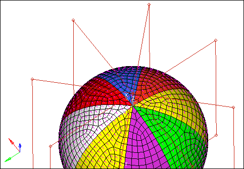
| 20. | Review additional ply angles, reselect elements, and enter a ply ID by clicking review. |
| Note: | Elements that do not have ply angles assigned will not be displayed. Ply directions are set through card images in the solver template; an example is PCOMP card for OptiStruct. |
See Also:
HyperMesh Tutorials


