In this tutorial, you will learn how to:
| • | Create loads and boundary conditions on geometry |
| • | Map the loads from geometry to elements |
| • | Modify the mesh and remap the loads to the new mesh |
Model Files
This exercise uses the c-channel0.hm file, which can be found in the hm.zip file. Copy the file(s) from this directory to your working directory.
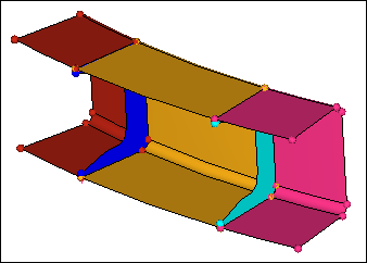
C-channel model in shaded mode
Exercise: Working with Loads on Geometry
Step 1: Retrieve the model file, c-channel0.hm.
In this tutorial, you will experiment with the export of the loads applied to geometry entities. Therefore, you will need to have a template loaded. In this step, load the OptiStruct user profile and retrieve the c-channel model. By loading the OptiStruct user profile, the template will be automatically loaded.
| 1. | Start HyperMesh Desktop. |
| 2. | In the User Profile dialog, select OptiStruct. |
| 4. | Open a model file by clicking File > Open > Model from the menu bar, or clicking  on the Standard toolbar. on the Standard toolbar. |
| 5. | In the Open Model dialog, open the c-channel0.hm file. A model appears in the graphics area. |
| Note: | The model's geometry is of a C-channel with two reinforcement ribs. The various surfaces are organized into several component collectors. |
Step 2: Create three load collectors for constraints, forces, and pressure loads.
In this step, create load collectors to organize constraints, forces, and pressure loads in.
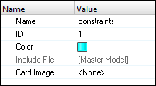
| 1. | In the Model browser, right-click and select Create > Load Collector from the context menu. HyperMesh creates and opens a load collector in the Entity Editor. |
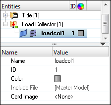
| • | For Name, enter constraints. |
| • | Click the Color icon, and select a new color for the load collector. |
| • | Set Card Image to <None>. |
| 3. | Repeat steps 2.1 and 2.2 to create two more load collectors named pressure and forces. |
| Note: | Different boundary conditions can now be created. |
Defining loads and boundary conditions on geometry.
In the following steps you will apply constraints, pressures, and forces to geometric entities in the model. You will first constrain the bottom portion of the c-channel using line data, then you will create pressure loads on the top surfaces. Lastly, you will apply forces to the eight corners of the surfaces defining the top of the c-channel.
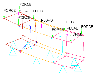
Constraints on lines, pressures on surfaces, and forces on fixed points
Step 3: Fully constrain the bottom eight lines of the c-channel using the Constraints panel.
| 1. | In the Model browser, Load Collector folder, right-click on constraints and select Make Current from the context menu. |
| 2. | Open the Constraints panel by clicking BCs > Create > Constraints from the menu bar. |
| 3. | Go to the create subpanel. |
| 4. | Set the entity selector to lines. |
| 5. | Select the eight lines defining the bottom portion of the c-channel as indicated in the following image. |
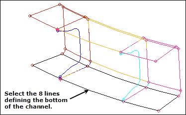
Lines to constrain
| 6. | In the size= field, enter 1. |
| Note: | This is the size of the icons that will be used to represent the constraints in the graphics area. |
| 7. | Clear the label constraints checkbox. |
| 8. | Select the dof1, dof2, dof3, dof4, dof5, and dof6 checkboxes. |
| Note: | The selected Dofs will be constrained. Dofs 1, 2, and 3 are x, y, and z translation degrees of freedom. Dofs 4, 5, and 6 are x, y, and z rotational degrees of freedom. |
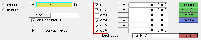
| 9. | Click load types = and select SPC. |
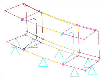
| 10. | Click create. HyperMesh applies constraints to the selected lines. Constraints are represented by triangular icons in the graphics area. |
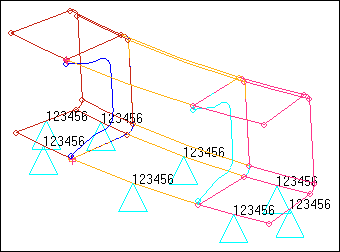
| 11. | Optional: Display the degrees of freedom labels by selecting the label constraints checkbox. |
| 12. | Exit the panel by clicking return. |
Step 4: Apply a pressure of 25 units normal to the top three surfaces using the Pressures panel.
| 1. | In the Model browser, Load Collector folder, right-click on pressure and select Make Current from the context menu. |
| 2. | Open the Pressures panel by clicking BCs > Create > Pressures from the menu bar. |
| 3. | Go to the create subpanel. |
| 4. | Set the first switch to entities. |
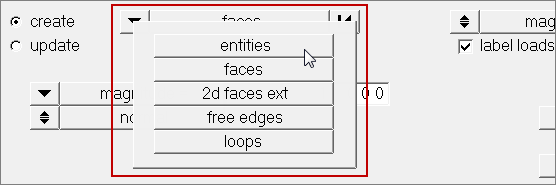
| 5. | Set the entity selector to surfs. |
| 6. | Select the three surfaces defining the top of the c-channel as indicated in the following image. |
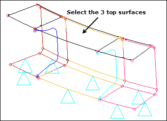
Surfaces to apply pressure to
| 7. | In the magnitude = field, enter –25 for the pressure. |
| Note: | Specifying a negative magnitude ensures that the pressure load pushes down on the surfaces. By default, pressure load are created normal to the surfaces. |
| 8. | Toggle the display of the pressures from magnitude % = to uniform size =. |
| Note: | Pressure loads are represented by arrows in the graphics area. You can input the size of the arrow as a value or as a percentage of the actual pressure load applied. In this exercise, you will specify its length as a certain number. |
| 9. | In the uniform size = field, enter 1. |
| Note: | This is the display size of the pressure arrows in the graphics area. |
| 10. | Clear the label loads checkbox. |
| Note: | In this exercise, you will not display the actual value of the pressure load in the graphics area. |
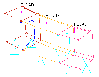
| 11. | Click load types = and select PLOAD. |
| 12. | Click create. HyperMesh applies pressure loads to the selected surfaces. Pressure loads are represented with an arrow and a label in the graphics area. |
| Note: | Labels can be template based (PLOAD here) or follow the HyperMesh terminology (P) as specified in the modeling subpanel of the Options panel. |
| 13. | Exit the panel by clicking return. |
Step 5: Create forces at the eight corners of the three top surfaces.
| 1. | In the Model browser, Load Collector folder, right-click on forces and select Make Current from the context menu. |
| 2. | Open the Forces panel by clicking BCs > Create > Forces from the menu bar. |
| 3. | Go to the create subpanel. |
| 4. | Set the entity selector to points. |
| 5. | Select the eight fixed points defining the corners of the c-channel’s top surfaces as indicated in the following image. |
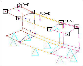
Fixed points to apply forces to
| 6. | Set the coordinate system toggle to global system. |
| 7. | Toggle the vector definition from magnitude % = to uniform size =. |
| 8. | In the uniform size = field, enter 1. |
| 9. | Clear the label loads checkbox. |
| 10. | In the magnitude = field, enter –15. |
| Note: | The minus sign is used to specify a direction opposite to the one you will select in the next step. |
| 11. | Under magnitude =, set the orientation selector to z-axis. |
| 12. | Click load types = and select FORCE. |
| 13. | Click create. HyperMesh creates a point force for each fixed point you selected, with the given magnitude in the z-direction. |
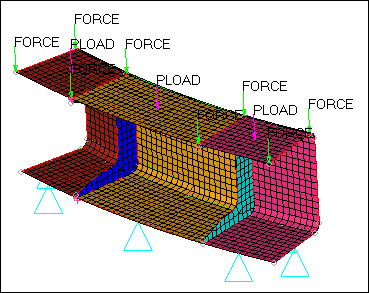
Loads on geometry
| 14. | Exit the panel by clicking return. |
| Tip: | If you organized some loads in the wrong load collector, use the Organize panel to move the loads into the right collector. |
In the previous steps you created various types of loads on various geometric entities: lines, surfaces, and fixed points. The ultimate goal is to apply these loading conditions to finite elements. In the following steps you will create the elements to apply the loading conditions to.
Step 6: Generate elements on the surfaces.
In this step, use the Automesh panel to create a quad dominant (mixed) mesh. The elements generated will be organized into their surface's component collector, which will avoid the need to set current component collectors.
| 1. | Open the Automesh panel by pressing F12. |
| 2. | Set the entity selector to surfs. |
| 3. | Click surfs >> displayed. |
| 4. | In the element size = field, enter 0.25. |
| 5. | Set the mesh type to mixed. |
| 6. | Toggle from elems to current comp to elems to surf comp. |
| Note: | This option ensures that the elements created will be organized into the surface’s component collector. |
| 7. | Set the meshing mode to automatic. |
| Note: | In this mode, HyperMesh automatically generates a mesh on the surfaces based on the element size and the type of elements selected. No further user input is required or can be supplied. |
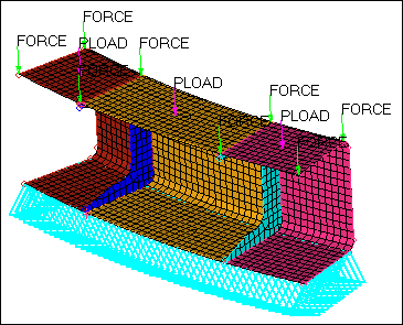
| 8. | Click mesh. HyperMesh creates a shell mesh on the surfaces. |
Meshed c-channel
| 9. | Exit the panel by clicking return. |
In this step, you created a shell mesh on the surfaces. In the following step you will map the loads that were applied to geometric entities to these finite elements.
Step 7: Map the loads from geometry to elements.
A load collector, just like component collectors, can store both loads on geometry and loads on finite elements. These two types of loads are separate and independent, and can therefore be manipulated independently. At this time, your load collectors contain loads only in their geom side. By mapping these loads on geometry to finite elements and using your existing loadcols, you will also populate their elems side.
In this step, use the Load on Geom panel to map the loads from the geometric entities (to which the geometric loads are applied) to the mesh associated with these geometric entities for the constraints and pressure load collectors.
| 1. | Open the Loads on Geometry panel by clicking BCs > Loads on Geometry from the menu bar. |
| 3. | Select the load collector, constraints. |
| 5. | Click map loads. HyperMesh maps the constraints previously applied to the lines to the nodes of the mesh associated to these lines. |
| Note: | These constraints are placed in the same load collector as the ones applied to the geometry, only in the elems portion. |
Constraints mapped to the elements
| 6. | Repeat steps 7.1 through 7.5 to map the pressure loadcol to the mesh. HyperMesh maps the pressure loads previously applied to the surfaces to the nodes of the mesh associated to these surfaces |
| Note: | These pressure loads are placed in the same load collector as the ones applied to the geometry. |
Step 8: Export the model to a solver deck.
When you export a model using an export template, only the loads on the mesh are exported. The loads on the mesh may have been applied directly to the mesh, mapped from geometry to the mesh, or both. You can use the Export tab to export loads to an ASCII solver-specific file (according to the loaded export template). The loads are exported as mesh loads.
Use the Custom template to determine which loads are exported. If all is selected, then all of the loads on the geometry that have not been mapped (if any) are mapped to the loads on the mesh, and all of the loads on the mesh are exported. If displayed is selected, then all of the displayed loads on the mesh (if any) are exported. All of the loads on the mesh associated with the displayed loads on the geometry (if any) are exported as well. If any of the loads on geometry are displayed and have not been mapped, they will automatically be mapped to the loads on the mesh and exported as well.
In this step, use the Model browser to ensure that only the already mapped loading conditions are exported. One load collector stores both the loads on the geometry and the loads on the mesh. The mesh (or multiple meshes) is associated with the geometric entities to which the loads on the geometry have been applied. Each load type is stored in a dedicated section of the same load collector.
Use the Display panel to separate or simultaneously visualize the loads on the mesh and the loads on the geometry. Turn off the display of the loads applied to the geometric entities to only display the loads applied to the mesh.
| 1. | In the Model browser, Load Collector folder, click  next to all of the loads to turn off the display of their geometry. next to all of the loads to turn off the display of their geometry. |
Load collector's geometry display turned off
| 2. | From the menu bar, click File > Export > Solver Deck. |
| 3. | In the File field, click  . . |
| 4. | In the Select OptiStruct file dialog, navigate to your working directory and save the file. |
| 5. | View advanced export options by clicking  next to Export options. next to Export options. |
| 6. | From the Export drop-down list, select Displayed. |
| 7. | Click Export. HyperMesh exports the model as an OptiStruct .fem input file. |
| Note: | Because you turned off the geometry display of the load collectors in your model, HyperMesh only exports the loads mapped previously. You may open the exported deck in any text editor to verify that no OptiStruct FORCE card has been exported in the deck. |
In this section you experimented with exporting loads applied to geometric entities and elements in the Export tab. You learned that with different combinations of the all/displayed options and loads displayed in the Model browser, you can control what information gets exported.
Step 9: Modify the mesh and remap the loads to the new mesh.
When loads are applied to geometry, you can re-applying them to different meshes as many times as you want. This functionality is particularly useful when you want to remesh a model without having to delete complicated loads or boundary conditions. After remeshing, you can easily remap loads or boundary conditions that have been applied to geometric entities to the new mesh, while loads applied to elements are automatically deleted when the elements themselves are deleted.
| Note: | If you delete geometric entities to which loads are applied to, the loads will be deleted. The deletion of geometric entities will not affect any loads applied to the mesh. |
In this step, you will remesh the surfaces.
| 1. | Go to the Automesh panel. |
| 2. | Click surfs >> displayed. |
| 3. | In the element size = field, enter 0.5. |
| 4. | Leave all other options used earlier unchanged. |
| 5. | Click mesh. The automesher deletes the existing elements, and creates a completely new set based on the new element size. |
| Note: | HyperMesh removes the loads that were applied to the initial mesh since the elements are no longer there. |
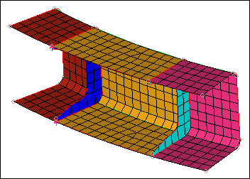
New mesh
Step 10: Map all the loads on geometry to the new mesh using the Load on Geom panel.
In this step you will remap the loads applied to the geometry to the new mesh.
| 1. | Open the Loads on Geometry panel by clicking BCs > Loads on Geometry from the menu bar. |
| 3. | Select the following load collectors: constraints, pressure, and forces. |
| 5. | Click map loads. HyperMesh applies the loading conditions initially defined for the geometric entities to the new mesh, and places the various loading conditions into the same load collector as the corresponding ones applied to the geometry. |
| Note: | You did not have to display these loads to map them. |
In this step, you experimented with the remapping of loads applied to geometric entities to a new mesh. Loads applied to geometric entities can be mapped several times to the different finite element entities attached to these geometric entities. For example, this functionality is useful in a situation where a mesh had to be changed, and it saved you from having to recreate loads on the elements.
Step 11 (Optional): Save your work.
With all of the exercises complete, you can save the model if desired.
Summary
In this tutorial, you used several boundary condition creation panels to generate constraints and various loading conditions on geometric entities. You then experimented with the mapping of these loads on the geometry to finite elements. You also familiarized yourself with the rules that govern the export of loads on geometric entities.
No consideration to the creation of specific card images that need to accompany the various loading conditions was given. For more information on how to generate the various loading conditions for different solvers, refer to the Modeling / Solver Specific section of the HyperMesh tutorials.
See Also:
HyperMesh Tutorials


