In this tutorial, you will learn how to:
| • | Load and create a Common representation and NVH representation for modal analysis |
| • | Import connector parts, add connector representations, and realize connectors |
| • | Edit part attributes using the Entity Editor to reflect design changes |
| • | Import and Export an assembly as a Solver Deck |
| • | Renumber entities using the ID-Manager |
| • | Check for errors using the Model Checker |
Model Files
This exercise uses the files located in the HM-3440 folder, which can be found in the hm.zip file. Copy the file(s) from this directory to your working directory.
Exercise
Step 1: Start HyperMesh Desktop and Load the OptiStruct User Profile
| 1. | Start HyperMesh Desktop. |
| 2. | In the User Profile dialog, select OptiStruct. |
Step 2: Import the PLMXML File
| 1. | Open the Import - BOM tab by clicking File > Import > BOM from the menu bar. |
| 2. | In the File field, open the BOM_input.xml file. |
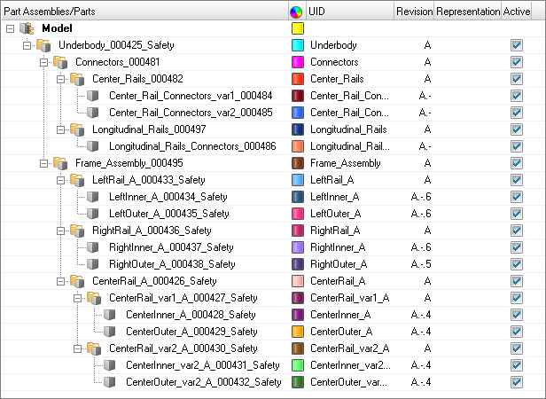
| 3. | Click Import. Part assemblies and parts are imported into the session. |
Step 3: Load and Create a Common Representation
Steps 3.4 - 3.6 below are optional as the Common representation can be created without loading the CAD into the session. Since the Common representation forms the basis of subsequent discipline specific mesh representations, its creation is a prerequisite for the next steps.
| 1. | Open the Part browser by clicking View > Browsers > HyperMesh > Part from the menu bar. |
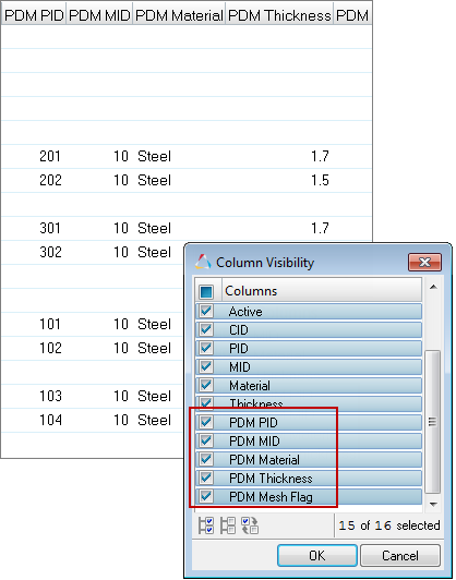
| 2. | In the Part browser, right-click and select Column Visibility from the context menu. |
| 3. | In the Column Visibility dialog, select the following columns: PDM PID, PDM MID, PDM Material, PDM Thickness, and PDM MeshFlag. These columns show the PDM metadata that is parsed upon importation of the PLMXML file. This information is also shown in the Entity Editor, PDM Data pane. |
| 4. | Right-click on the Frame_Assembly_000495 part assembly and select Representations > Load > from Session from the context menu. |
| 5. | In the Change Representations dialog, Load tab, select the CAD representation. |
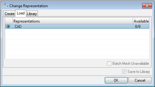
| 6. | Click OK. All available CAD representations are imported into the session. |
| 7. | Right-click on the Frame_Assembly_000495 part assembly and select Representations > Create from the context menu. |
| 8. | In the Change Representations dialog, Create tab, select Common (0/8). |
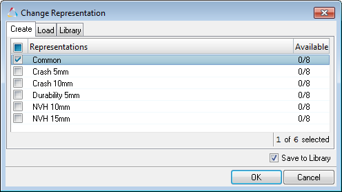
| 9. | Click OK. Available CAD representations are sent to the BatchMesher for processing. |
| Note: | In the case of sheet metal parts, the BatchMesher extracts the midsurface from the solid CAD representation. |
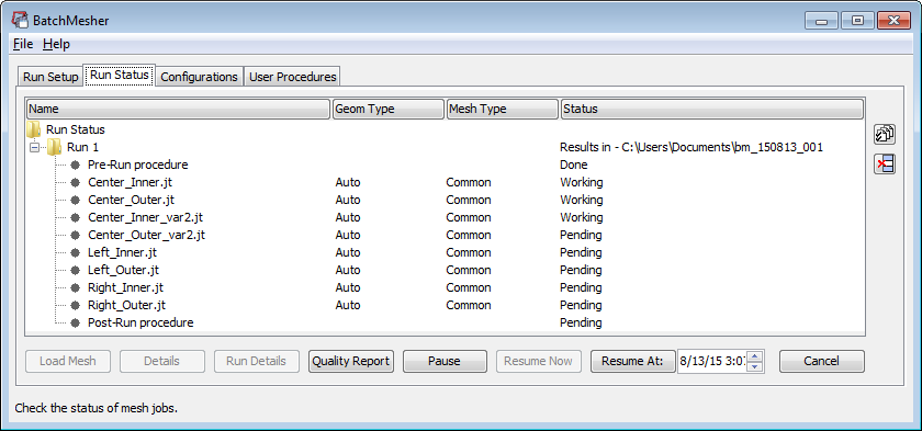
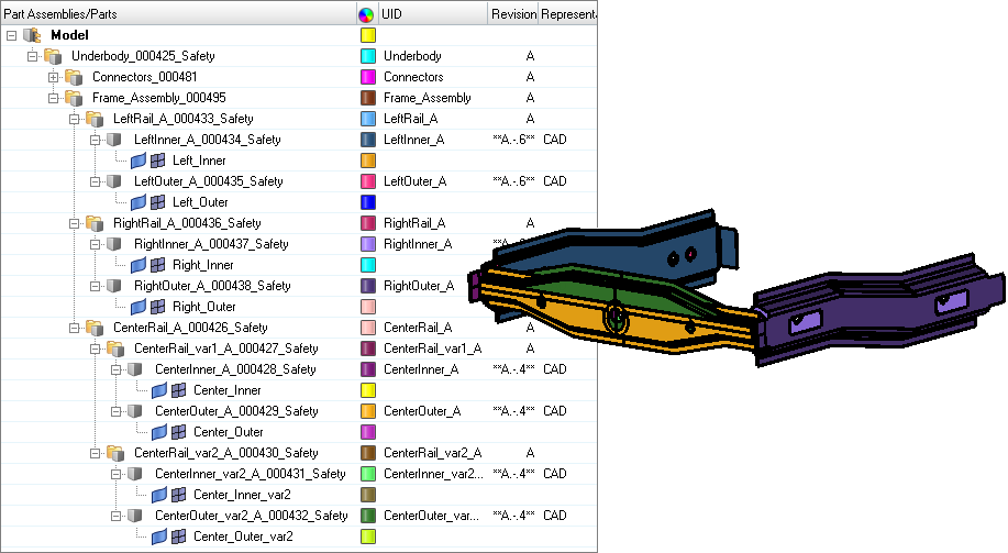
| 10. | In the BatchMesh dialog, click Yes to load the new representations for the eight parts. |
| 11. | Repeat steps 3.7 - 3.10 to create NVH10 and NVH15 representations. |
Step 6: Add Connector Representations
| 1. | In the Part browser, right-click on the Connectors_000481 part assembly and select Representations > Load > from Session from the context menu. |
| 2. | In the Change Representation dialog, Load tab, select the Connector representation. |
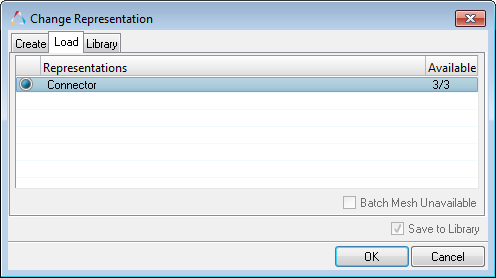
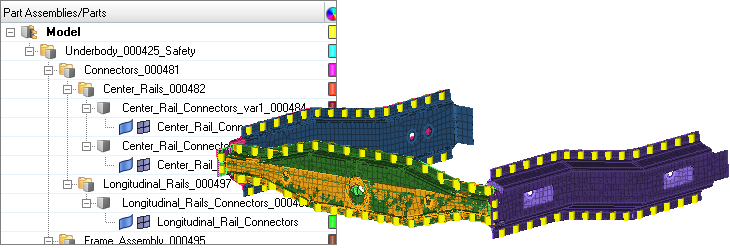
| 3. | Click OK. Components containing connectors are appended to their corresponding parts. |
Step 7: Design change - modify Center Rail part attributes
| 1. | In the Part browser note the PID of parts CenterInner_var2_A_000431_Safety and CenterOuter_var2_A_000432_Safety. |
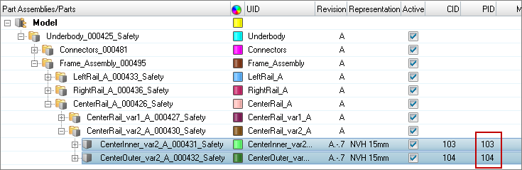
| 2. | In the Model browser, switch the view mode to Properties. |
| 3. | Select PID 103 and 104. The Entity Editor opens and displays the two properties common corresponding attributes. |
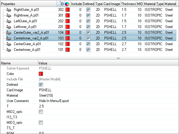
| 4. | In the Entity Editor, T field, enter 3.0. |
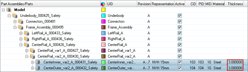
| 5. | In the Part browser, notice the attribute modification you made is updated in the Thickness columns. Save these changes to ensure that they are available if the current representation is unloaded. |
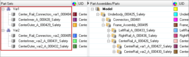
Step 8: Create Part Sets
Create part sets Var1 and Var2 for Variant 1 and Variant 2 in the Part Set view.
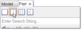
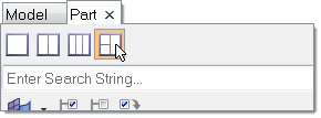
| 1. | In the Part browser, enable the Part Set view. |
| a. | In the Part Set view, right-click and select Create > Part Set from the context menu. |
| b. | Name the part sets Var1 and Var2. |
| 3. | Group common and unique parts by dragging-and-dropping parts from the Part view onto the part set. |
Var 1:
| • | Center_Rail_Connectors_var1_000484 |
| • | CenterInner_A_000428_Safety |
| • | CenterOuter_A_000429_Safety |
Var2:
| • | Center_Rail_Connectors_var2_000485 |
| • | CenterInner_var2_A_000431_Safety |
| • | CenterOuter_var2_A_000432_Safety |
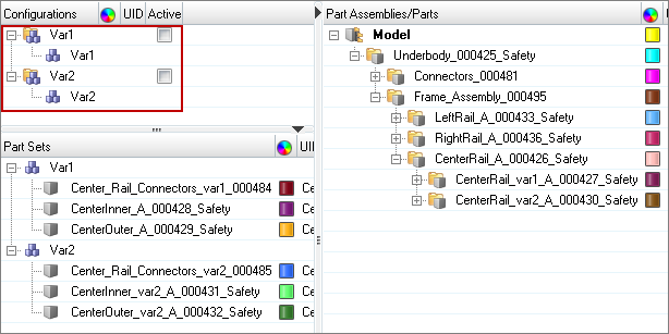
Step 9: Create Configurations
Create configurations Var1 and Var2 for part sets Var1 and Var2 in the Configuration view.
| 1. | In the Part browser, enable the Configuration view. |
| 2. | Create two configurations. |
| 3. | In the Part Set view, right-click and select Create > Configuration from the context menu. |
| 4. | Name the configurations Var1 and Var2. |
| 5. | Group part sets that are unique by dragging-and-dropping part sets from the Part Set view onto the configuration. |
| a. | Group the Var1 part set into the Var 1 configuration. |
| b. | Group the Var2 part set into the Var 2 configuration. |
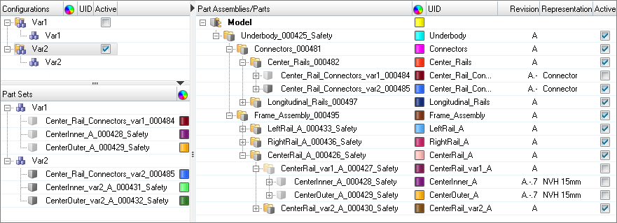
Step 10: Activate the Var 2 Configuration
| 1. | In the Part browser's Configuration view, Active column, enable the checkbox for Var 2. |
All of the parts, part assemblies, components, and part sets not associated with Var 2 become inactive.
Step 11: Export Assembly as a Solver Deck
| 1. | Open the Export – Solver Deck tab by clicking File > Export > Solver Deck from the menu bar. |
| 2. | In the File field, enter frame_var2_model.fem. |
| • | Set Export to Custom to ensure that inactive parts are not written to the solver deck. |
| • | Under Comments, select the Part Assemblies/Parts checkbox. |
| 5. | Save the model as frame_assembly.hm. |
Step 12: Import Assembly Solver Deck
| 1. | Start a new HyperMesh Desktop session. |
| 2. | Open the Import – Solver Deck tab by clicking File > Import > Solver Deck from the menu bar. |
| 3. | In the File field, locate the frame_var2_model.fem solver deck. |
| 5. | In the Part browser, verify that the BOM was imported correctly. |
| Note: | All part assembly and part metadata in the original model should be present, with the exception of the Representation name. |
Step 13: Import Realizations
| 1. | Open the Import - Model tab. |
| 2. | Click  , then open the Realizations.hm file. , then open the Realizations.hm file. |
| 3. | The Spotweld component, in the Realizations.hm file, references a material that has the same ID as a material that already exists in the current session, therefore under Entity Management, set Materials to Keep Existing Attributes. |
| 4. | Click Import. Connector parts are imported and organized in the Part browser. |

Step 14: Realize Connectors
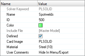
| 1. | In the Part browser, right-click on the Spotwelds component and select Make Current from the context menu. |
| 2. | In the Part browser, right-click on the Longitudinal_Rail_Connectors component and select Hide from the context menu. The display of the component’s connectors is turned off in the graphics area enabling you to get a better visual of each component's connectors. |
| 3. | Open the Connector browser by clicking View > Browsers > HyperMesh > Connectors from the menu bar. |
| 4. | In the Connector Entity browser, select the acm (shell gap) connector folder. |
| 5. | In the Entity Editor, set Property Script to no/skip post script. |
| Note: | Connector links are defined via Parts to ensure that connectors realize even if you, accidentally, renumber all of the entities in the model. |
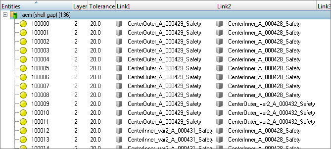
| 6. | In the Connector Entity browser, select all of the connectors. |
| 7. | Right-click on the selected connectors and select Rerealize from the context menu. |
| 8. | In the Part browser, right-click on the Spotwelds part and select Isolate Only from the context menu. Verify that the realized FE resides in the Spotwelds component. |
Step 15: Renumber Nodes and Elements
| 1. | Open the ID-Manager by clicking Tools > ID-Manager from the context menu. |
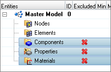
| 2. | In the ID-Manager, select Components, Properties, and Materials then right-click and select Exclude from the context menu. |
| 3. | For the Master Model, enter 1,000,000 in the Min field and 1,500,000 in the Max field. |
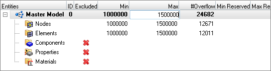
| 4. | Correct ID overflow by right-clicking on the Master Model and selecting Correct > Overflow from the context menu. |
Step 16: Run the Model Checker
| 1. | Open the Model Checker by clicking Tools > Model Checker > OptiStruct. |
| 2. | In the Model Checker tab, click  . . |
| 3. | Verify that the model is error free. |
Step 17: Export the Solver Deck
| 1. | From the menu bar, click File > Export > Solver Deck. |
| 2. | In the Export – Solver Deck tab, File field, enter the file name frame_var2_assembled.fem. |
| 3. | Under Export options, Comments, select the Part Assemblies/Parts checkbox. |


