In this tutorial, you will learn how to:
| • | Load the Ansys user profile and CAD data. |
| • | Mesh all of the surfaces at once, specifying element sizes and an element type. |
| • | Import an Equivalent Fibersim model. |
| • | Define the dummy properties and assign them to the mesh. |
| • | Define an orientation for the component |
| • | Use the Ply Realization and distribution table option |
| • | Create/Edit a distribution table |
| • | Use the Ply thickness visualization -3D representation option |
Model Files
This exercise uses the pillar_w_ncf.CATPart file, which can be found in <hm.zip>/interfaces/ansys/. Copy the file(s) from this directory to your working directory.
Exercise
Step 1: Load the ANSYS User Profile
A set of standard user profiles is included in the HyperMesh installation. They include: OptiStruct, RADIOSS, Abaqus, Actran, ANSYS, LS-DYNA, MADYMO, Nastran, PAM-CRASH, PERMAS, and CFD. When a user profile is loaded, applicable utility menus are loaded, unused panels are removed, unneeded entities are disabled in the Find, Mask, Card and Reorder panels and specific adaptations related to the Ansys solver are made.
| 1. | Start HyperMesh Desktop. |
| 2. | In the User Profile dialog, set the user profile to Ansys. |
Step 2: Load the HyperMesh Model for this Tutorial
| 1. | From the menu bar, click File > Import > Geometry. |
| 2. | In the Import tab, set File type to CATIA. |
| 3. | Click  . . |
| 4. | In the Select CATIA file dialog, open the pillar_w_ncf.CATPart file. |
| 5. | Click Import. HyperMesh imports geometry data only. |
| Note: | You will import the Ply and Composite data later in this tutorial. |
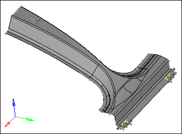
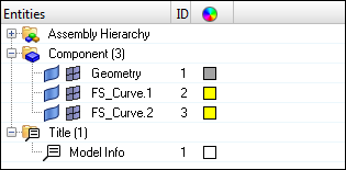
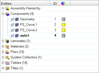
| 6. | In the Model browser, review the model's contents. |
Step 3: Mesh all of the Surfaces at Once, Specifying Element Sizes and Element Type
| 1. | To open the Automesh panel, do one of the following: |
| • | From the menu bar, click Mesh > Create > 2D AutoMesh. |
| • | From the main menu, go to the 2D page and click automesh. |
| 2. | Go to the size and bias subpanel. |
| 3. | Set the entity selector to surfs. |
| 4. | Click surfs >> displayed. |
| 5. | In the element size= field, enter 5. |
| 6. | Set mesh type to mixed. |
| 7. | Set the mesh mode to interactive. |
| 8. | Set the elements to surf comp/elements to current comp toggle to elems to current comp. |
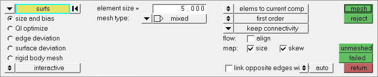
Size and bias subpanel settings for steps 2.3 through 2.8.
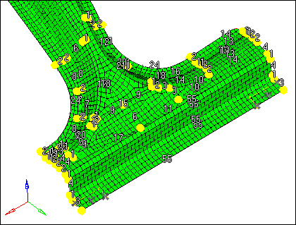
| 9. | Click mesh. The meshing module opens. |
| Note: | You should now be in the density subpanel of the meshing module. There is node seeding and a number on each surface edge. The number indicates the number of elements that were created along the edge. |
| 10. | Accept the mesh by clicking return. |
| 11. | From the menu bar, click File > Save As > Model. |
| 12. | In the Save Model As dialog, navigate to your working directory and save the HyperMesh database with the name pillar_w_ncf_FINAL.hm. |
Step 4: Load the Ply Information from FiberSim
| 1. | From the menu bar, click File > Import > Geometry. |
| 2. | In the Import tab, set File type to FiberSim. |
| 3. | Click . |
| 4. | In the Select FiberSim file dialog, open the pillar.h5 file. |
| 5. | Click Import. HyperMesh imports and populates the database with laminate data (ply book and ply stacking data), composite material information, each ply data (triangular elements spanning a single ply), and a coordinate system. |
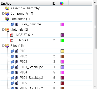
| 6. | In the Model browser, review the model's contents. |
| 7. | Make elements and feature lines transparent by clicking  on the Visualization toolbar. on the Visualization toolbar. |
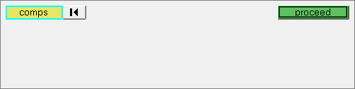
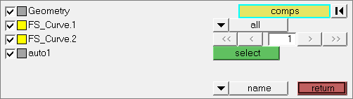
| 8. | In the panel area, click comps. |
| 9. | Select the components, Geometry and auto1. |
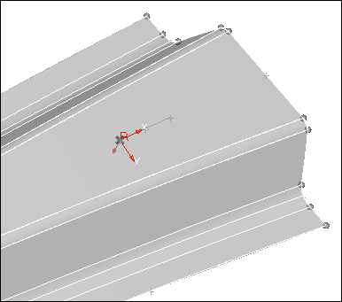
| 11. | Use the transparency slider to review the system collector imported by the FiberSim model. |
| 13. | On the Visualization toolbar, click  to shade the elements and mesh lines, and click to shade the elements and mesh lines, and click  to shade the geometry and surface edges. to shade the geometry and surface edges. |
| 14. | In the Model browser, turn off the display of geometry for all of the components. |
Step 5: Review and Edit Element Normals
| 1. | Open the Normals panel by clicking Mesh > Check > Elements > Normals from the menu bar. |
| Note: | Element normals need to be changed to match the Z direction (red color). |
| 2. | Set the first switch to elems. |
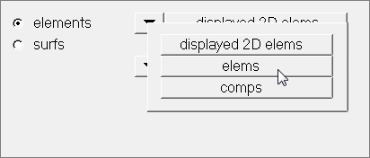
| 3. | Click elems >> displayed. |
| 4. | Set the vector display/color display toggle to color display. |
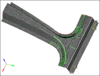
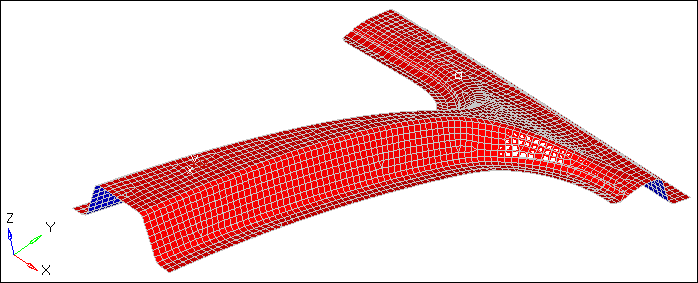
| 5. | Click display. HyperMesh displays, on each side of the part, the element normals using the colors red and blue. |
| Note: | The red side of the elements is the positive normal direction Z, while the blue side is the negative normal direction. |
| 6. | Set orientation to elem. |
| 7. | Select one element that has the right direction. This element will be used as the model for all of the other elements. |
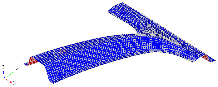
| 8. | Click adjust. All of the elements are set in the same normal direction. |
| 9. | Optional. If the blue color is in the Z direction, click elems >> displayed and then click reverse. All of the elements are set in the right normal direction (red). |
| 10. | Click return to exit the panel. |
Step 6: Realize Ply Geometry Shape
| 1. | In the Model browser, right-click on the Plies folder and select Realize from the context menu. |
| 2. | In the Ply Realization dialog, click Component. |
| 3. | In the panel area, click comps. |
| 4. | Select all of the components. |
| 7. | Set Projection options to FiberSim drape map by proximity method. |
| 8. | Set Search Criterion to Element centroid. |
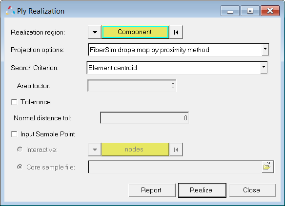
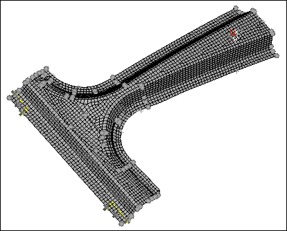
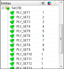
| 9. | Click Realize. This process takes each FiberSim Ply data and finds the FE elements which are bounded by the ply boundaries, and transfers the ply directions, draping data, and ply orientation into FE elements. This process also converts geometry plies into FE plies. At the end of realization, HyperMesh creates sets containing FE elements for each ply. |
Step 7: Add an Element Type
| 1. | In the Model browser, right-click and select Create > Sensor from the context menu. HyperMesh creates and opens a sensor (Et Type) in the Entity Editor. |
| 2. | In the Entity Editor, enter a name and ID, and select a color. |
| 3. | By default, Element Type is set to SHELL181. |
SHELL181
| • | Suitable for analyzing thin to moderately-thick shell structures. It is a 4-node element with six degrees of freedom at each node: translations in the x, y, and z directions, and rotations about the x, y, and z-axes. (If the membrane option is used, the element has translational degrees of freedom only). The degenerate triangular option should only be used as filler elements in mesh generation. |
| • | Well-suited for linear, large rotation, and/or large strain nonlinear applications. Change in shell thickness is accounted for in a nonlinear analysis. In the element domain, both full and reduced integration schemes are supported. SHELL181 accounts for follower (load stiffness) effects of distributed pressures. |
| • | May be used for layered applications for modeling laminated composite shells or sandwich construction. The accuracy in modeling composite shells is governed by the first order shear deformation theory. |
| 4. | To simulate the element stiffness, set the stress stiffening option, extra displacement shapes, extra stress output, pressure loading, mass matrix, stress stiffness matrix, define the element coordinate system and specify the data storage using the respective keyopts, click Create/Edit. |
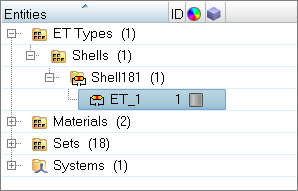
| 5. | Open the Solver browser by clicking View > Browsers > HyperMesh > Solver from the menu bar. |
| 6. | Review the new element type you just created. |
Step 8: Update the Component with Element Type
All elements in the model are in the Geometry component. In order for all elements in the Geometry component to be exported with the element type SHELL181, you must attach the element type defined in the previous step to the Geometry component. The desired element type is SHELL181, which is why you were instructed to create SHELL181 elements in the previous step. In this step, you will attach the sensor entity, with SHELL181 elements attached, to the Geometry component.
| 1. | In the Model browser, Component folder, select Geometry. The Entity Editor opens and displays the component's corresponding data. |
| 2. | In the Entity Editor, set Card Image to HM_COMP. |
| 3. | For Type, click Unspecified >> Sensor. |
| 4. | In the Select Sensor dialog, select sensor1 and click OK. |
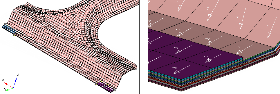
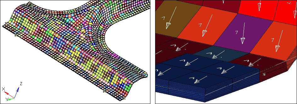
Step 9: Ply 2D Visualization
In this step you will verify FE plies thickness and orientation in HyperMesh.
| 1. | On the Visualization toolbar, set the element color mode to  (visualize elements by property). (visualize elements by property). |
| 2. | On the Visualization toolbar, set the layer representation mode to  (Composite Layers with Fiber Direction). (Composite Layers with Fiber Direction). |
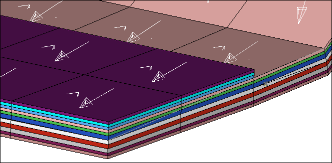
| 3. | In the Model browser, Hide and Show each Ply. |
| 4. | On the Visualization toolbar, set the element representation mode to  (2D Detailed Element Representation). (2D Detailed Element Representation). |
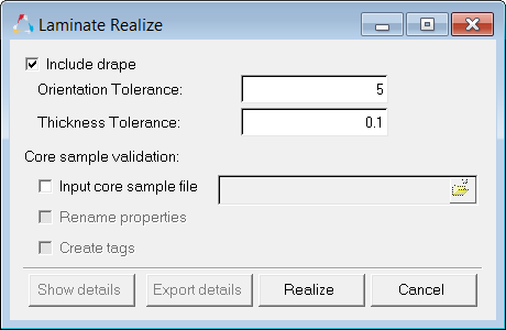
Step 10: Laminate Realize - Ply Based Model
| 1. | In the Model browser, right-click on the Laminate folder and select Realize from the context menu. |
| 2. | In the Laminate Realize dialog, accept the default settings and click Realize. HyperMesh creates a property for each stack, and assigns it to a component. |
| 3. | On the Visualization toolbar, set the element color mode to  . . |
| 4. | In the Model browser, Sections folder, you will see the shell sections that were created when you realized the laminate. |
| 5. | Click on a section to display its corresponding details in the Entity Editor. |
| 6. | In the Entity Editor, under PLIES, next to Data: TK, click  . . |
| 7. | In the PLIES dialog, review the number of plies, thickness, orientation, and material data. |
Step 11: Export the Eeck to ANSYS *.cdb Format.
| 1. | Open the Export tab by click File > Export > Solver Deck from the menu bar. |
| 2. | Set File type to Ansys. |
| Note: | If you are in the ANSYS user profile, HyperMesh automatically sets the File type to Ansys and loads ANSYS as the default Template. |
| 3. | In the File field, navigate to your working directory and save the file as pillar_w_ncf-FINALhm.cdb. |
See Also:
HyperMesh Tutorials


