A free sizing optimization on composite materials is run to determine the optimal ply shapes and fiber orientation/material selection. After this optimization phase is run, the next step is to:
| • | Interpret the optimized ply shapes, |
| • | Smooth the ply boundaries, and |
| • | Setup a subsequent, more detailed size optimization run to determine the number of plies that are required for each ply shape and material. |
With the input file for the size optimization phase automatically generated by OptiStruct, handling the ply interpretation and smoothing process can be a tedious, manual process. Altair's ply shape interpretation functionality streamlines this design interpretation process, by allowing the interpretation of optimized ply shapes from a composite free sizing optimization.
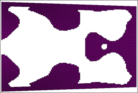
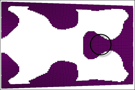
During the interpretation process, the boundaries of the ply shapes are smoothed, and options are available to create separate ply entities for disconnected ply patches and for the treatment of very small ply coverage regions.
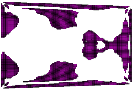
Additionally, after the smoothing and interpretation process is complete, a ready-to-run OptiStruct input deck is generated using the smoothed ply shapes and updated ply definitions--all while preserving the material definition, properties and fiber orientation. The following set of images depicts the new ply shape interpretation functionality.

Figure 1: Example ply shape from free size optimization

Figure 2: Smoothed ply boundary after running OSSmooth

Figure 3: Additional treatment of small regions
The smooth iterations option defines the number of smoothing iterations to be run. Greater smoothing can be achieved by increasing the number of iterations. The default number of iterations is 20.
The small region option determines how very local and small ply coverage regions are treated. Regions smaller than the threshold value will be eliminated during the smoothing process. Two methods of determining what constitutes a small region are available:
| • | Area ratio: local region area / total design area (real value between 0.0 and 1.0. Default=0.01) |
| • | Elem count: small region identified by number of elements (integer >=0. Default=15) |
The split disconnected option can be used to create separate ply entities from disconnected ply coverage regions.


