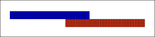
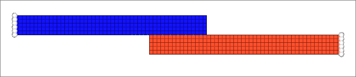
In this tutorial you will learn how to set up edge to edge contacts. In HyperMesh, you can create contact pairs manually or with the Autocontact tool. For this tutorial, you will learn how to set up contacts manually. You will create edge to edge contacts between two flat plates. One of the plates will act as a sliding plate (Contact edge), and the other will act as a stationary (Target edge).
The steps mentioned in this tutorial are only applicable for HyperMesh 14.0.130 and on.
In this tutorial, you will:
| • | Load the ANSYS user profile. |
| • | Retrieve the HyperMesh model for this tutorial. |
| • | Create a constraints load collector. |
| • | Create edge to edge contacts. |
| • | Apply the constraints to the model. |
| • | Apply displacement to the two end nodes of the component "contact". |
| • | Activate control cards for Nonlinear Analysis Solution Control. |
| • | Export the deck to ANSYS *.cdb format. |
Model Files
This exercise uses the chapter2_3.hm file, which can be found in <hm.zip>/interfaces/ansys/. Copy the file(s) from this directory to your working directory.
Exercise
Step 1: Load the ANSYS User Profile
| 1. | Start HyperMesh Desktop. |
| 2. | In the User Profile dialog, set the user profile to Ansys. |
Step 2: Retrieve the HyperMesh Model for this Tutorial
| 1. | From the menu bar, click File > Open > Model. |
| 2. | In the Open Model dialog, open the chapter2_3.hm file. A model loads in the graphics area. |
Step 3: Open the Contact Browser
| 1. | Open the Contact browser from the menu bar by clicking View > Browsers > HyperMesh > Contact. |
| 2. | In the first pane of the browser, mask the target component to enable better selection of contact surfaces on the contact component. |
Step 4: Create Contact (Master) Surface
| 1. | In the first pane of the Contact browser, right-click and select Create > Contact Surfaces from the context menu. HyperMesh creates and opens a contact surface in the Entity Editor. |
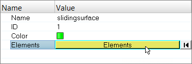
| 2. | In the Entity Editor, for Name, enter slidingsurface. |
| 3. | For Elements, click 0 Elements >> Elements. |
| 4. | In the panel area, set the first selector to add shell edges. |
| 5. | Select reverse normals. |
| 6. | For face angle, enter 30.0. |
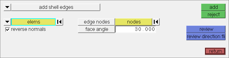
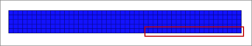
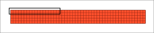
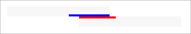
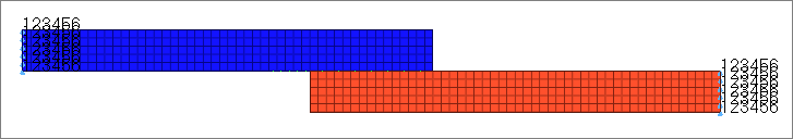
| 7. | Set advanced selection to elems, then select the free edges indicated in the image below. |
| Tip: | Quickly select elements with window selection by pressing SHIFT while clicking and dragging your mouse. |
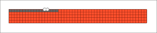
| 8. | Using the nodes selector, select a couple nodes along the free edge you have selected to identify the edge on which contact surface are to be created. |
| 9. | Click add. All of the edges of the selected elements are added to the surface. |
| 10. | Click return to exit the panel. |
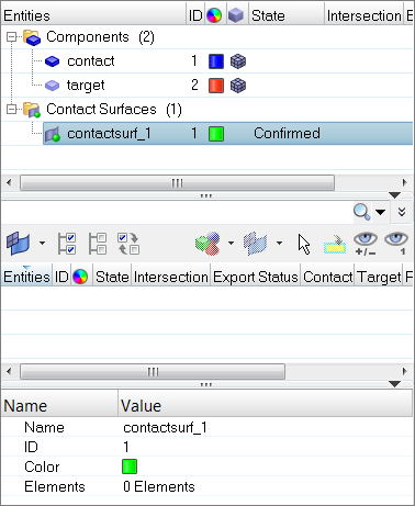
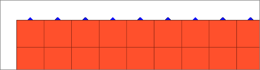
| 11. | In the Contact browser, right-click on slidingsurface and select Review from the context menu. Review the contact surface you just created. |
| 12. | Isolate the contact surface for a better visual display. The surface created here will be considered master (contact) surfaces during analysis. |
Step 5: Create Target (Slave) Surface
| 1. | Unmask the target component, and mask the contact component and slidingsurface contact surface. |
| 2. | In the first pane of the Contact browser, right-click and select Create > Contact Surfaces from the context menu. HyperMesh creates and opens a contact surface in the Entity Editor. |
| 3. | In the Entity Editor, for Name, enter targetsurface. |
| 4. | For Elements, click 0 Elements >> Elements. |
| 5. | In the panel area, set the first selector to add shell edges. |
| 6. | Select reverse normals. |
| 7. | For face angle, enter 30.0. |
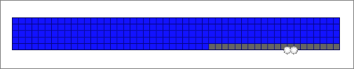
| 8. | Set advanced selection to elems, then select the free edges indicated in the image below. |
| Tip: | Quickly select elements with window selection by pressing SHIFT while clicking and dragging your mouse. |
| 9. | Using the nodes selector, select two nodes along the free edges you have selected to identify the edge on which contact surface are to be created. |
| 10. | Click add. All of the edges of the selected elements are added to the surface. |
| 11. | Click return to exit the panel. |
| 12. | In the Contact browser, right-click on targetsurface and select Review from the context menu. Review the contact surface you just created. |
| 13. | Isolate the contact surface for a better visual display. The surface created here will be considered slave (target) surfaces during analysis. |
Step 6: Create a Contact Pair
| 1. | In the second pane of the Contact browser, right-click and select Create > Contact Pair from the context menu. HyperMesh creates and opens a contact pair in the Entity Editor. |
| 2. | In the Entity Editor, enter a name and ID, and select a color for the contact pair. |
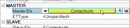
| 3. | Attach the contact (master) surface. |
| a. | For Master IDs, click 0 Contactsurfs >> Contactsurfs. |
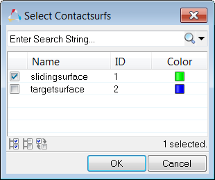
| b. | In the Select Contactsurfs dialog, select slidingsurface and click OK. |
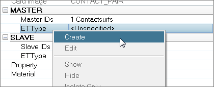
| c. | Under MASTER, right-click on ETType, and select Create from the context menu. |
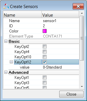
| d. | In the Create Sensors dialog, define the sensor and click Close. |
| • | By default, the Element Type is set to CONTA171. |
| • | Enable KeyOpt12, then select 0-Standard from the list. Keyopts determine the behavior of contacts during analysis. KeyOpt12 defines the type of contact. |
| 4. | Attach the target (slave) surface. |
| a. | For Slave IDs, click 0 Contactsurfs >> Contactsurfs. |
| b. | In the Select Contactsurfs dialog, select targetsurface and click OK. |
| c. | Under SLAVE, right-click on ETType, and select Create from the context menu. |
| d. | In the Create Sensors dialog, define the sensor and click Close. |
| • | By default, the Element Type is set to Targe169. |
| • | Enable KeyOpt4, then select 111-ROTZ, UY, UX from the list. The target (slave) surface will be exported with the elements type TARGE169. |
| 5. | Create and attach the contact property. |
A contact property for a pair is always required, as the solver recognizes the pair only by the property ID associated with the master and slave surfaces. Same property IDs are shared by the master and slave surfaces. If a property ID is missing for a contact surface, then it will not considered as part of the contact pair and it will not recognized.
| a. | Right-click on Property and select Create from the context menu. |
| b. | In the Create Properties dialog, define the property and click Close. |
| 6. | Create and attach the contact material. |
The properties MU (coefficient of friction) and EMIS (Thermal Emissivity) are available to define. If you are creating a structural contact, select MU; if you are creating a thermal contact, select EMIS. In this exercise you will be creating a structural contact.
| a. | Right-click on Material and select Create from the context menu. |
| b. | In the Create Materials dialog, define the material and click Close. |
| • | Select the MU (coefficient of friction) checkbox. |
| • | Under MP_MU_LEN=, next to Data: C, click  . . |
| • | In the MP_MU_LEN= dialog, enter 0.45 and click Close. |
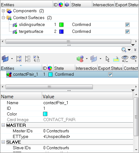
Step 7: Review the Contact Pair
| 1. | In the second pane of the Contact browser, select the contact pair to display its entity details in the Entity Editor. |
| 2. | Right-click on the contact pair and select Review from the context menu. The contact area displays. |
| 3. | Right-click on the contact pair again and select Reset Review from the context menu. |
Step 8: Create a Constraints Load Collector
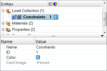
| 1. | In the Model browser, right-click and select Create > Load Collector from the context menu. HyperMesh creates and opens a load collector in the Entity Editor. |
| 2. | For Name, enter Constraints. |
| 3. | Click the Color icon, and select a color for the load collector. |
| 4. | You do not need to assign a card image for this load collector. |
Step 9: Apply Constraints to the Model
| 1. | Open the Constraints panel by clicking BCs > Create > Constraints from the menu bar. |
| 2. | Select all of the dof (degree of freedom) checkboxes. |
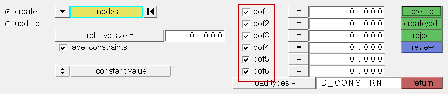
| 3. | Set the entity selector to nodes. |
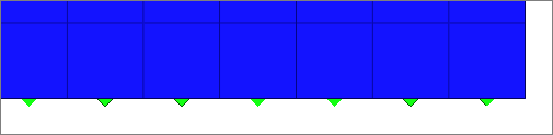
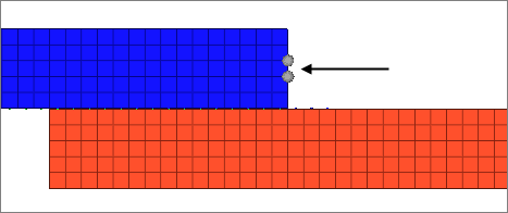
| 4. | Select the nodes on the left end of the contact component and on the right end of the target component as indicated in the following image. |
| 5. | In the relative size= field, enter 2. |
Step 10: Apply a Displacement Constraint to the Two Mid-Nodes of the Component Contact
In this step you should still be in the Constraints panel.
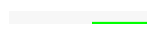
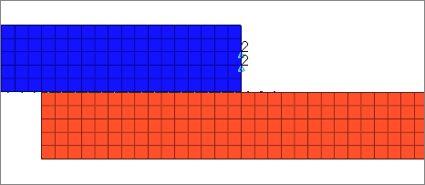
| 1. | Select the two mid nodes at the end of the contact component as indicated in the following image. |
| 2. | Clear all of the dof checkboxes except for dof2. |
| 3. | In the dof2= field, enter -5.0 for the displacement value of the selected mid nodes at the component contact in the global –Y direction. |
| 5. | Click return to exit the Constraints panel. |
Step 11: Activate Control Cards for Nonlinear Analysis Solution Control
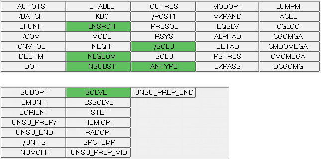
| 1. | Open the Control Cards panel by clicking Setup > Create > Control Cards from the menu bar. |
| 2. | Specify the analysis type and restart the status by clicking ANTYPE. |
| 3. | Set type to STATIC and status to NEW. |
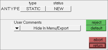
| 4. | Click return to go back to the control cards page. |
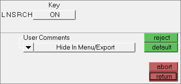
| 5. | Activate a line search to be used with Newton-Raphson by clicking LNSRCH. |
| 6. | Under Key, click OFF and then select ON from the list. |
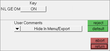
| 8. | To include large-deflection effects in a static or full transient analysis, click NLGEOM. |
| 9. | Under Key, click OFF and then select ON from the list. |
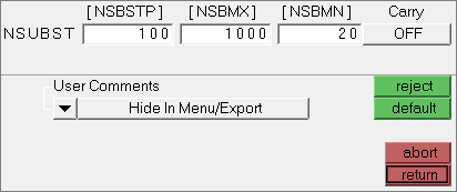
| 11. | Specify the number of sub steps to be taken for this load step by clicking NSUBST. |
| 12. | Click [NSBSTP] and enter 100 in the editable field. |
| Note: | NSBSTP is the number of sub steps to be used for this load step. |
| 13. | Click [NSBMX] and enter 1000 in the editable field. |
| Note: | NSBMX is the maximum number of sub steps to be taken (minimum time step size) if automatic time stepping is used. |
| 14. | Click [NSBMN] and enter 20 in the editable field. |
| Note: | NSBMN is the minimum number of sub steps to be taken (maximum time step size) if automatic time stepping is used. |
| 15. | Verify that Carry is set to OFF. |
| 17. | Exit the PREP7 preprocessor and enter the SOLU preprocessor by clicking /SOLU. |
| 19. | Solve the model by clicking SOLVE. |

| Note: | When the color of the control card button is green, the card exists in the database and will be written when the Export Data panel is used with the current template. |
| 22. | Save your model by clicking File > Save > Model from the menu bar. |
Step 12: Export the Model
HyperMesh can export ANSYS model data in script format. The following steps explain the process of exporting an ANSYS model from HyperMesh.
| 1. | Open the Export tab by clicking File > Export > Solver Deck from the menu bar. |
| 2. | Set File type to Ansys. |
| Note: | If you are in the ANSYS user profile, HyperMesh will automatically set the File type to Ansys. |
| 3. | In the File field, navigate to your working directory and save the file as exercise2b.cdb. |
See Also:
HyperMesh Tutorials


