Model and local mesh controls define the meshing mode, element size, element type, and additional parameters used to create a mesh of shell elements using surface geometry or existing shell elements.
| Note: | In order to run a meshing job, at least one model mesh control must be defined. |
|
When defining model and local mesh controls, select a mesh mode to use during automatic meshing to determine the type of meshing to perform. For more information on the different mesh modes, refer to Mesh Modes. The mesh mode for model controls can be changed at any time. However, for local controls, the mesh mode is defined only at the time of creation.
Generates mesh using elements of a uniform size that you specify.
Parameters
Parameter
|
Description
|
Use Model Settings
|
Sets all of the main parameters from the model control.
For local controls only.
|
Element Size
|
Average element size. The length of any active (shared or free) surface edge divided by the element size determines the number of elements to place along that edge.
|
Element Type
|
Type of elements used to create mesh during automatic meshing.
For more information, see Mesh Types.
|
Element Order
|
First order creates elements using a linear shape function; Second order creates elements using a polynomial shape function.
For local controls, this is inherited from the model control and cannot be set independently.
|
|
Parameter
|
Description
|
Organization
|
Destination Component
|
Original stores newly created elements in the component to which the surface belongs; Current stores newly created elements in the "current" active component.
Valid only for model controls.
|
Mesh Connectivity
|
Determines how newly created elements and any adjacent existing elements are connected.
| • | Keep uses existing nodes on any shared boundary edges. |
| • | Redo re-seeds existing nodes along the boundary of the newly created mesh to optimize mesh quality. |
| • | Break ignores existing adjacent elements and generates mesh according to the element size and type you specified. |
Valid only for model controls.
|
Flow
|
Align
|
Produces a more orthogonal quad-dominant mesh.
Only available when the Element Type is set to Mixed.
Here, there is no flow alignment
|
Flow alignment is used, producing straighter rows of elements
|
|
Size
|
Enforces the global mesh element size with minimal min/max element size variations.
Only available when Element Type is set to Mixed and Flow: Align is enabled.
|
Mapping
|
Size
|
Keeps elements roughly the same size.
|
Skew
|
Prevents mesh from producing highly-skewed elements.
|
Other - Surface Based Automeshing Only
|
Link Opposite Edges
|
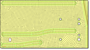
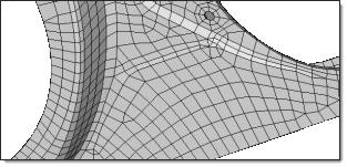
Links mesh settings on opposing edges of rectangular surfaces. Changes applied to one linked edge will be applied to the other. By default, the maximum aspect ratio (AR) to allow between large and small edge sizes of linked edges is 2.11.
Manually specify an aspect ratio by setting Aspect Ratio Less Than to User Specified. Increasing the value adds more surfaces to the linked chain, whereas decreasing the value removes some surfaces from the linked chain.
Mesh without link opposite edges selected.
|
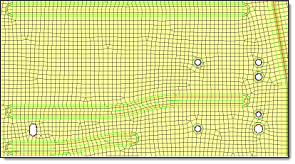
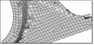
Mesh with link opposite edges selected and Aspect Ratio Less Than set to Auto.
|
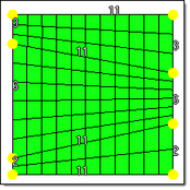
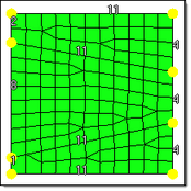
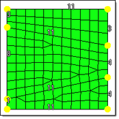
Mesh with link opposite edges selected and Aspect Ratio Less Than set to User Specified, with an Aspect Ratio of 8.0.
|
|
|
Parameter
|
Description
|
Auto Features
|
Defines logical faces when using existing finite elements as a basis for automeshing.
| • | Connected detects features based on the specified feature angle, and makes additional effort to void any "orphan" or non-closed feature lines. It works similarly to Auto Detect, but includes a more rigorous check to combine small areas and avoid creating features that end abruptly or do not connect to any other features. |
Before re-meshing
|
After re-meshing with connected features selected
|
| • | Auto Detect detects features based on the specified feature angle. |
| • | Surface Edges automatically detects and utilizes geometric lines associated with selected elements as features in the re-meshing operation. |
Before re-meshing
|
After re-meshing with surface edges selected
|
| • | None ignores extra features defined by any of the above methods. |
|
User Features
|
A selection of user-created 1D elements which define features that need to be captured along with any feature angle-based features. Only 1D elements should be selected here, as any other element selections are ignored.
|
Anchor Nodes
|
Nodes that will remain and be re-used in the new mesh. Anchor nodes are "fixed" so that the automesher cannot move or replace them; in essence, they are exceptions to the re-meshing operation, and the new mesh must utilize them.
|
|
|
An iterative automatic mesh generation method driven by element quality criteria.
Parameters
Parameter
|
Description
|
Use Model Settings
|
Sets all of the main parameters from the model control.
For local controls only.
|
Element Size
|
Average element size. The length of any active (shared or free) surface edge divided by the element size determines the number of elements to place along that edge.
|
Element Type
|
Type of elements used to create mesh during automatic meshing.
For more information, see Mesh Types.
|
Element Order
|
First order creates elements using a linear shape function; Second order creates elements using a polynomial shape function.
For local controls, this is inherited from the model control and cannot be set independently.
|
Criteria File
|
Specify a criteria file that will be used to automatically generate criteria.
|
|
Parameter
|
Description
|
Organization
|
Destination Component
|
Original stores newly created elements in the component to which the surface belongs; Current stores newly created elements in the "current" active component.
Valid only for model controls.
|
Mesh Connectivity
|
Determines how newly created elements and any adjacent existing elements are connected.
| • | Keep uses existing nodes on any shared boundary edges. |
| • | Redo re-seeds existing nodes along the boundary of the newly created mesh to optimize mesh quality. |
| • | Break ignores existing adjacent elements and generates mesh according to the element size and type you specified. |
Valid only for model controls.
|
Flow
|
Align
|
Produces a more orthogonal quad-dominant mesh.
Only available when the Element Type is set to Mixed.
Here, there is no flow alignment
|
Flow alignment is used, producing straighter rows of elements
|
|
Size
|
Enforces the global mesh element size with minimal min/max element size variations.
Only available when Element Type is set to Mixed and Flow: Align is enabled.
|
Mapping
|
Size
|
Keeps elements roughly the same size.
|
Skew
|
Prevents mesh from producing highly-skewed elements.
|
Other - Surface Based Automeshing Only
|
Smooth Across Common Edges
|
Node smoothing moves nodes across adjacent surface edges whose feature angle is less than the value specified. When selected, strict adherence to the geometry of the surface edges in not enforced for non-feature edges; some deviation from the geometry can occur.
|
|
Parameter
|
Description
|
Auto Features
|
Defines logical faces when using existing finite elements as a basis for automeshing.
| • | Connected detects features based on the specified feature angle, and makes additional effort to void any "orphan" or non-closed feature lines. It works similarly to Auto Detect, but includes a more rigorous check to combine small areas and avoid creating features that end abruptly or do not connect to any other features. |
Before re-meshing
|
After re-meshing with connected features selected
|
| • | Auto Detect detects features based on the specified feature angle. |
| • | Surface Edges automatically detects and utilizes geometric lines associated with selected elements as features in the re-meshing operation. |
Before re-meshing
|
After re-meshing with surface edges selected
|
| • | None ignores extra features defined by any of the above methods. |
|
User Features
|
A selection of user-created 1D elements which define features that need to be captured along with any feature angle-based features. Only 1D elements should be selected here, as any other element selections are ignored.
|
Anchor Nodes
|
Nodes that will remain and be re-used in the new mesh. Anchor nodes are "fixed" so that the automesher cannot move or replace them; in essence, they are exceptions to the re-meshing operation, and the new mesh must utilize them.
|
|
|
Determines how far the mesh elements can deviate from the actual edges of the surfaces meshed, or when in the case of re-meshing elements, deviation from inferred edges based on features.
Parameters
Parameter
|
Description
|
Use Model Settings
|
Sets all of the main parameters from the model control.
For local controls only.
|
Minimum Size
|
Minimum allowable element size.
|
Maximum Size
|
Maximum allowable element size.
|
Maximum Deviation
|
Allowable deviation between the element edge and the surface edge. To meet this requirement, element edge lengths along a curved surface edge are reduced as needed down to a lower limit set by the minimum element size.
|
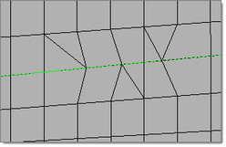
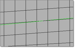
Maximum Feature Angle
|
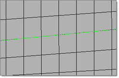
Maximum angle across which elements can be maintained. When two adjacent elements’ normals exceed this angle, a new set of nodes is created between them to maintain clean feature lines. Using higher value results in elements spanning the feature line.
With an appropriate value, the features lines are preserved.
|
If the feature angle is too high, the feature lines are blurred.
|
|
Element Type
|
Type of elements used to create mesh during automatic meshing.
For more information, see Mesh Types.
|
Element Order
|
First order creates elements using a linear shape function; Second order creates elements using a polynomial shape function.
For local controls, this is inherited from the model control and cannot be set independently.
|
|
Parameter
|
Description
|
Organization
|
Destination Component
|
Original stores newly created elements in the component to which the surface belongs; Current stores newly created elements in the "current" active component.
Valid only for model controls.
|
Mesh Connectivity
|
Determines how newly created elements and any adjacent existing elements are connected.
| • | Keep uses existing nodes on any shared boundary edges. |
| • | Redo re-seeds existing nodes along the boundary of the newly created mesh to optimize mesh quality. |
| • | Break ignores existing adjacent elements and generates mesh according to the element size and type you specified. |
Valid only for model controls.
|
Flow
|
Align
|
Produces a more orthogonal quad-dominant mesh.
Only available when the Element Type is set to Mixed.
Here, there is no flow alignment
|
Flow alignment is used, producing straighter rows of elements
|
|
Mapping
|
Size
|
Keeps elements roughly the same size.
|
Skew
|
Prevents mesh from producing highly-skewed elements.
|
Other - Surface Based Automeshing Only
|
Link Opposite Edges
|
Links mesh settings on opposing edges of rectangular surfaces. Changes applied to one linked edge will be applied to the other. By default, the maximum aspect ratio (AR) to allow between large and small edge sizes of linked edges is 2.11.
Manually specify an aspect ratio by setting Aspect Ratio Less Than to User Specified. Increasing the value adds more surfaces to the linked chain, whereas decreasing the value removes some surfaces from the linked chain.
Mesh without link opposite edges selected.
|
Mesh with link opposite edges selected and Aspect Ratio Less Than set to Auto.
|
Mesh with link opposite edges selected and Aspect Ratio Less Than set to User Specified, with an Aspect Ratio of 8.0.
|
|
|
Parameter
|
Description
|
Auto Features
|
Defines logical faces when using existing finite elements as a basis for automeshing.
| • | Connected detects features based on the specified feature angle, and makes additional effort to void any "orphan" or non-closed feature lines. It works similarly to Auto Detect, but includes a more rigorous check to combine small areas and avoid creating features that end abruptly or do not connect to any other features. |
Before re-meshing
|
After re-meshing with connected features selected
|
| • | Auto Detect detects features based on the specified feature angle. |
| • | Surface Edges automatically detects and utilizes geometric lines associated with selected elements as features in the re-meshing operation. |
Before re-meshing
|
After re-meshing with surface edges selected
|
| • | None ignores extra features defined by any of the above methods. |
|
User Features
|
A selection of user-created 1D elements which define features that need to be captured along with any feature angle-based features. Only 1D elements should be selected here, as any other element selections are ignored.
|
Anchor Nodes
|
Nodes that will remain and be re-used in the new mesh. Anchor nodes are "fixed" so that the automesher cannot move or replace them; in essence, they are exceptions to the re-meshing operation, and the new mesh must utilize them.
|
|
|
Generates mesh within the limits of element deviation from input elements.
Parameters
Parameter
|
Description
|
Use Model Settings
|
Sets all of the main parameters from the model control.
For local controls only.
|
Minimum Size
|
Minimum allowable element size.
When there are model and local mesh controls for surface deviation, and the minimum size of neighboring mesh controls are different, the minimum size will automatically propagate from the smaller mesh size to neighboring surfaces.
|
Maximum Size
|
Maximum allowable element size.
|
Growth Rate
|
Determines how rapidly elements can increase in size as they are created further and further away from features.
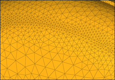
Elements further from the features grow larger with each row.
|
Span Angle
|
Controls the element size at curve input. The smaller the angle, the more refined curvature will be and the more preserved the input shape will be. By default span angle is 25.0 degrees.
In the green circle below, β is the span angle of the edge ab. The length of ab is less than 2R( sin β/2 ).
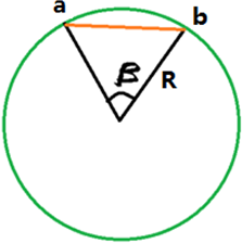
Valid only for element-based controls.
|
Feature Angle
|
Determines which features to preserve. The mesher identifies features internally and preserves/refine them based on the defined feature angle.
Valid only for element-based controls.
|
Element Order
|
First order creates elements using a linear shape function; Second order creates elements using a polynomial shape function.
For local controls, this is inherited from the model control and cannot be set independently.
|
|
Parameter
|
Description
|
Organization
|
Mesh Connectivity
|
Determines how newly created elements and any adjacent existing elements are connected.
| • | Keep uses existing nodes on any shared boundary edges. |
| • | Redo re-seeds existing nodes along the boundary of the newly created mesh to optimize mesh quality. |
| • | Break ignores existing adjacent elements and generates mesh according to the element size and type you specified. |
Valid only for model controls.
|
|
Parameter
|
Description
|
Auto Features
|
Defines logical faces when using existing finite elements as a basis for automeshing.
| • | Connected detects features based on the specified feature angle, and makes additional effort to void any "orphan" or non-closed feature lines. It works similarly to Auto Detect, but includes a more rigorous check to combine small areas and avoid creating features that end abruptly or do not connect to any other features. |
Before re-meshing
|
After re-meshing with connected features selected
|
| • | Auto Detect detects features based on the specified feature angle. |
| • | Surface Edges automatically detects and utilizes geometric lines associated with selected elements as features in the re-meshing operation. |
Before re-meshing
|
After re-meshing with surface edges selected
|
| • | None ignores extra features defined by any of the above methods. |
|
User Features
|
A selection of user-created 1D elements which define features that need to be captured along with any feature angle-based features. Only 1D elements should be selected here, as any other element selections are ignored.
|
Refine Features
|
Apart from capturing the features if refine feature is turned enabled, you can define the mesh size to be applied to features selected/found by any of the above methods.
|
|
|
Generates mesh to represent the topology of a rigid object. Available only for surface-based meshing.
Parameters
Parameter
|
Description
|
Use Model Settings
|
Sets all of the main parameters from the model control.
For local controls only.
|
Minimum Size
|
Minimum allowable element size.
|
Maximum Size
|
Maximum allowable element size.
|
Maximum Deviation
|
Allowable deviation between the element edge and the surface edge. To meet this requirement, element edge lengths along a curved surface edge are reduced as needed down to a lower limit set by the minimum element size.
|
Maximum Feature Angle
|
Maximum angle across which elements can be maintained. When two adjacent elements’ normals exceed this angle, a new set of nodes is created between them to maintain clean feature lines. Using higher value results in elements spanning the feature line.
With an appropriate value, the features lines are preserved.
|
If the feature angle is too high, the feature lines are blurred.
|
|
Element Type
|
Type of elements used to create mesh during automatic meshing.
For more information, see Mesh Types.
|
Element Order
|
First order creates elements using a linear shape function; Second order creates elements using a polynomial shape function.
For local controls, this is inherited from the model control and cannot be set independently.
|
|
Parameter
|
Description
|
Organization
|
Destination Component
|
Original stores newly created elements in the component to which the surface belongs; Current stores newly created elements in the "current" active component.
Valid only for model controls.
|
|
|


