BL + Tetra model mesh controls define boundary layer and tetrameshing parameters.
Parameters
Available parameters vary depending on the Method you select: Simple, Advanced, User Defined. For Simple and Advance mesh controls, refer to Link to CFD Tetramesh Panel.
Parameter
|
Description
|
Basic Surface Mesh Treatment
|
Fixed prohibits selected elements from being modified.
Float enables 2D base elements to be modified, if necessary. Generally 2D base elements with NoBL are modified when refinement zones are defined and/or when the BL imprints on them.
|
BL Definition
|
When enabled, parameters will be editable and will be applied to all selections. When disabled, a BL definition will not be applied at model level.
Local controls will override the BL definition at the model level.
|
First Layer Thickness
|
Specify the thickness of the first boundary layer.
|
First Layer Thickness Method (A)
|
Constant enables a constant thickness to be defined for the first boundary layer of the selection.
As Factor of Base 2D Elements enables a factor, which will be multiplied by the average element size, to be defined. The first layer height for each element equals the average element size multiplied by the factor. This option is useful when the size of 2D elements varies significantly and a constant first layer height is not needed. With this factor, a smooth BL to tetramesh transition for all elements can be achieved.
|
Growth Rate
|
Determines how rapidly elements can increase in size as they are created further and further away from features.
Elements further from the features grow larger with each row.
|
BL Growth Rate Method (A)
|
Constant enables a constant ratio to be defined, which determines how boundary layers grow.
Acceleration enables a growth acceleration for boundary layers to be defined beyond the first few layers. This option acts as a growth rate on the growth rate, but only after the first few initial boundary layers. A Start Acceleration from Layer must be defined first, and then from that layer the acceleration will be started. An Acceleration to the initial growth rate and a Maximum Growth Rate must also be defined.
By default, the first two boundary layers grow by the growth rate described above. However, subsequent layers grow by the growth rate multiplied by the acceleration factor. Thus, if d is the initial thickness, r is the initial growth rate, and a is the acceleration rate, then the thicknesses of the successive layers are d, d*r, d*r*(r*a), d*r*(r*a)^2, and so on.
Aspect Ratio Based enables the growth rate definition for boundary layers to be based on the defined aspect ratio of the final layer. After the first few initial boundary layers, if this type of growth rate method is selected, the rest of the BL will grow to achieve the user defined Final layer height / base ratio.
|
BL Thickness Control (UD)
|
Enables this option to enter either the Number of layers or the Total BL thickness.
|
Second Group (UD)
|
Helps to get a smooth transition between BL layers and the tet core more quickly, by defining a higher growth rate.
|
Final Layer Height/Base Ratio
|
Defines the ratio between the total boundary layer thickness and the average element size of the base surface elements.
|
BL Stopping Criteria (A)
|
Determines what to do when BL has reached the defined criteria for Final Layer Height/Base Ratio.
| • | Chop Off Layers chops off the BL if elements reach the aspect ratio criteria. |
| • | Keep Growing Gr=1 allows the BL to grow until the neighboring elements begin to grow, even if elements reach the aspect ratio criteria with GR =1. |
|
Number of Layers (S)
|
Defines the total number of layers to be generated using the specified first layer thickness and growth rate.
|
Hexa Transition Mode
|
Simple Pyramid transitions from a BL hexahedral’s quad face to a tetrahedral core mesh using one pyramid element. The height of pyramid elements is controlled by a simple transition ratio parameter, which represents the ratio between the transition pyramid height and the characteristic size of the base quad.
All Prism splits quad elements in the surface mesh into two trias each so that there will be no need to transition from quad faces to tria faces when transitioning from the last boundary layer to the tetrahedral core. This mode is very important when there are quad elements on areas with (low) distributed BL thickness ratios, because in such areas the thickness of the transition elements (for example simple pyramid) was not taken into account when doing the interference study to assign distributed BL thickness ratio to those elements.
All Tetras generates tetra elements only in the boundary layer and splits the quad elements of the surface mesh into tria elements.
|
Boundary Layer Only
|
Generates only the boundary layer, stopping before the tetrahedral core is generated. Adjacent surface meshes are also modified to reflect changes introduced by the boundary layer thickness. A collector named ^CFD_trias_for_tetramesh is created and is typically used to generate the inner core tetrahedral mesh using the Tetramesh parameters subpanel.
Boundary layer elements are placed in a collector named CFD_boundary_layer; core tetrahedral elements are placed in a collector named CFD_Tetramesh_core. Both collectors are automatically created if they do not exist. However, if these collectors do exist, it is recommended that you empty them before meshing; otherwise there will be more than one set of elements occupying the same physical volume. If you mesh the volume in several steps (multi-volume meshing), it is recommended that you empty the collector before generating the mesh for the next adjacent volume.
|
|
Parameter
|
Description
|
Element Size Limits
|
Specify the average, minimum, maximum, or minimum/maximum size of the tetramesh.
| • | None. The maximum element size will be determined by the input 2D elements size and growth rate. |
| • | Average Size. Enter the average element size for the tetramesh. If you enter 10, then element sizes will range between 6.6 and 14. |
| • | Maximum Size. Tetra element will not be above this size. |
| • | Minimum Size. Tetra elements will not be below this size. |
| • | Minimum/Maximum Size. Tetra elements will not be below or above this size. |
Maximum element size guidelines:
| • | When the input shell element size is close to the user defined maximum tetra size, then the maximum tetra size is used in averaged sense (therefore the actual maximum size may be larger than defined). This prevents a large number of elements from being created. |
| • | When the input shell element size is sufficiently different then the user defined maximum tetra size, the maximum size will be enforced. |
|
Quality
|
Normal uses the standard tetra-meshing algorithm.
Optimize Speed uses an algorithm for faster meshing. Use this option if element quality considerations are less important than mesh generation time.
Optimize Quality spends more time optimizing element quality, and employs the volumetric ratio, or CFD skew measurement for tetras as a quality measure. Use this option if your solver is sensitive to element quality.
|
Growth Rate
|
The Growth rate parameter works as follows: if d is the initial thickness and r is the initial growth rate, then the thicknesses of the successive layers are d, d*r, d*r^2, d*r^3, d*r^4, and so on.
If element quality is important and you are not concerned with the total number of elements being created, then Interpolate will produce the best results because the element size changes smoothly and therefore the element quality is better.
Different default values are specified for the various growth rate options:
| • | User Controlled: You can define your own value when you select this option. |
|
Pyramid Transition Ratio
|
Defines the relative height of pyramid elements used for the transition from hexa elements in the boundary layer to the tetra elements in the core.
|
Smoothing
|
Applies an extra stage of calculation to improve overall mesh quality. Additional smoothing and swapping steps will be performed and tetra elements will be split to achieve a smoother mesh transition. If tetra elements are used in the boundary layer, then those elements will be excluded from smoothing to maintain the original distribution.
|
Use Number of Layers
|
Defines the number of tetrahedral layers to generate.
When enabled, the Tetramesher ensures the tetracore contains, at minimum, the specified number of tetra layers in the model. This functionality ensures a certain mesh resolution in case of close proximity or thin channels.
When generating multiple tetrahedral layers, keep the following restrictions in mind:
| • | Do not generate more than three or four layers, unless you refine the surfaces to have a fine mesh at close proximity areas. |
| • | Layer meshes will not be created near narrow strip surfaces, as the current algorithm does not alter the surface mesh given. |
|
|
Parameter
|
Description
|
Boundary Layer Propagation
|
Treatment at Sharp Edges
|
Node collapse. Collapses BL at baffles or sharp corners below the defined angle.
Multiple normal. Grows multiple normals around baffles or sharp corners below the defined angle. If two adjacent elements enclose an angle smaller than the threshold (sharp edge pointing into the volume), normals will be computed on that edge and the boundary layer will consider those normals.
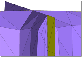
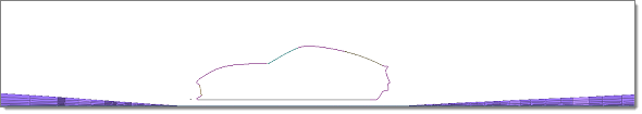
Node collapse option selected (baffle is yellow)
|
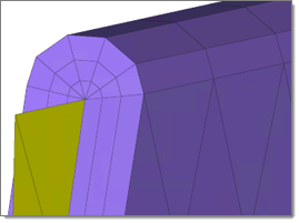
Multiple normal selected (baffle is yellow)
|
|
Sharp Edge Angle
|
Defines the threshold of angles below which the BL should be collapsed.
|
Minimum Imprint Angle from BL to Non-BL
|
Controls which cases to imprint BL entities on without BL components. If the angle between the BL component and the non BL component is high, imprinting will create high aspect ratio elements. If the angle between BL and Non-BL entities (component elements) is less than the imprint angle or greater than (180-imprint angle), then the BL will collapse rather than imprinting on non-BL entities.
Recommended range: 6-10
|
Max Layer Difference Between Neighbors
|
Controls the maximum layer difference between neighboring elements. This parameter helps avoid situations where all BLs collapse at once, and also provides smooth BL transitions in cases of BL truncation. A good value for this parameter is 1/4 of the total BL layers. The value specified also depends on layer height.
Recommended range: Depends on how many layers you are growing.
|
Proximity
|
Maximum BL Compression
|
Enables BL compression, or squeezing, when there is not enough space available for the BL to grow. The BL will try to compress by the max BL compression factor first. For example, if the original total BL height is defined as 1, with a 0.4 max BL compression, the BL layers will try to be compressed until 0.6 of the total height is reached. Once the BL is compressed to this value, the mesher will start chopping off layers if there is not enough space.
A value of zero enforces no BL compression, which is useful when you want to maintain the BL height; a value of one enables the maximum possible compression.
Recommended range: 0-0.6
|
Minimum BL Thickness/Base Ratio
|
Due to close proximity, the BL will sometimes only be able to generate one to two layers (a very small total BL height at that location). At that location, it might be possible that the transition between BL layers and the tetra core is bad. With this factor, if the total BL height is less than the defined factor base size, all of the BL layers will be chopped off.
By default, this value is zero, which disables the effects of this parameter.
|
Minimum Tetcore/Final Layer Height Ratio
|
Controls the minimum height of the tet core as a factor of the final layer height.
After creating the BL in close proximity, there will be a small space available for tetramesh. This results in high aspect ratio tetra elements.
Recommend value: 1.3 (default)
|
Boundary Layer Quality
|
Generation Method
|
Controls the growth of boundary layers.
| • | Optimize Quality uses a set of meshing parameters, which ensures a good quality boundary layer in most cases. |
| • | Optimize Speed chooses meshing parameters in a way that the meshing time is minimized and an acceptable boundary layer quality is achieved. |
|
Maximum Cell Skewness
|
Chops off BL cells exceeding the defined maximum cell skewness. This parameter prevents the generation of highly skewed elements.
The tetra mesher sometimes creates better quality elements compared to the BL mesher. If your input 2D mesh has bad element quality and topology, it is recommended that you define a higher value.
Recommended range: 0.8 - 0.95
|
Minimum Normalized Jacobian
|
Chops off BL cells exceeding the defined minimum normalized Jacobian. This parameter prevents the generation of negative elements.
Recommended range: 0.05 - 0.2
|
Tetra Quality
|
Element Quality Target
|
Select an element criteria and threshold. After the tetrameshing step, a mesh optimization step will be performed to fulfill the defined threshold for the selected element criteria.
Available quality criteria include: Volume Skew, Tetra Collapse, and Cell Squish.
|
Volume Setup
|
Validate 2D Input
|
Checks BL elements before tetrameshing to rectify if there is anything wrong with the input (intersecting elements) provided for the tetramesh.
|
Fix Invalid 2D Element
|
Fixes invalid elements (at present only unoffsettable nodes) before volume meshing.
For unoffsettable nodes (where BL collapses if not smooth), the connected elements will be smoothed where the BL will be generated.
|
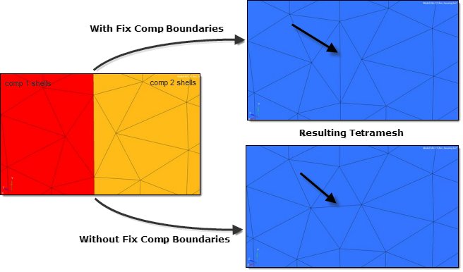
Fix Component Boundaries
|
Anchor nodes are maintained during CFD tetrameshing, so that the new mesh adheres to them. 1D elements can be selected instead of nodes if you need a tetra element edge at a certain location. Select this option when certain mesh nodes or edges are required on a certain location, such as for post-processing purposes.
If the Float option is selected for some boundary regions, surface shell edges will be swapped during mesh generation. However, this prevents the swapping of edges between two components.
|
Update Input Shells
|
Automatically updates the shells on all boundaries after meshing. Updated shell elements are placed in the initial boundary shell components.
|
Fill Void
|
Meshes all volumes. If your geometry includes volumes inside of another volume, enable this parameter.
For example, if you had a sphere inside of a larger sphere, enabling this parameter would cause the volume of the inner sphere as well as the volume between the two spheres to be meshed.
|
Other
|
Anchor Node
|
Nodes that will remain and be re-used in the new mesh. Anchor nodes are "fixed" so that the automesher cannot move or replace them; in essence, they are exceptions to the re-meshing operation, and the new mesh must utilize them.
|
|
|


