In this tutorial, you will learn how to set up an Abaqus input file in HyperMesh for obtaining the linear static response of a cradle and bracket assembly subjected to a 100 kN load on the bracket, with the cradle’s ends fully constrained. Specifically, you will learn how to:
| • | View images of keywords and data lines in HyperMesh as they appear in the Abaqus input file |
| • | Create and edit Abaqus materials and section properties |
| • | Select Abaqus entity types for HyperMesh element and load configurations |
| • | Create loads and boundary conditions for model data (*KINEMATIC COUPLING and *BOUNDARY) |
| • | Create an Abaqus step containing title, analysis procedure, parameters, *CLOAD on bracket, and output requests |
| • | Export a model to an Abaqus formatted input file |
| Note: | The units millimeters and kilonewtons (mm, kN) are used in this tutorial. |
|
Model Files
This exercise uses the bracket_cradle.hm file, which can be found in <hm.zip>/interfaces/abaqus/. Copy the file(s) from this directory to your working directory.
Exercise
Follow the steps below to start HyperMesh using the Abaqus template, and load the model.
Step 1: Load the Abaqus user profile and model
| 1. | Start HyperMesh Desktop. |
| 2. | In the User Profile dialog, set the user profile to Abaqus, Standard3D. |
| 3. | Open a model file by clicking File > Open > Model from the menu bar, or clicking  on the Standard toolbar. on the Standard toolbar. |
| 4. | In the Open Model dialog, open the bracket_cradle.hm file. |
The bracket_cradle.hm file contains the following Abaqus model data:
| • | ELSET bracket modeled with penta (C3D6) and hexa (C3D8) elements |
| • | ELSET cradle modeled with tria (S3) and quad (S4) elements |
| • | Two *KINEMATIC COUPLING entities at the bracket’s bottom bolt holes |
| • | *SOLID SECTION property for ELSET bracket with the aluminum material associated to it |
Understanding the relationship between Abaqus and HyperMesh entities
You can use HyperMesh card images to view images of keywords and data lines for defined Abaqus entities as interpreted by the loaded template. The keywords and data lines appear in the Abaqus input file as you see them in the card images. Additionally, for some card images, you can define and edit various parameters and data items for the corresponding Abaqus keyword.
Review and edit card images by clicking  on the Collectors toolbar. You can also review and edit the card image for many entities from the panel in which they are created. Most of the card images are also accessible from the Model browser by right-clicking on the entity and selecting Card Edit from the context menu, or simply left-clicking on the entity displays it in the Entity Editor.
*ELEMENT with Sectional Property
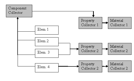
The Abaqus keyword *ELEMENT, TYPE = <type>, ELSET = <name>, is defined by Abaqus elements collected in a HyperMesh component collector. One *ELEMENT keyword is written to the Abaqus input file for each element type in the component. The name of the ELSET is the name of the component.
If a property is assigned to a component, the ELSET name of that sectional property will be the name of the component collector. If properties are directly assigned to elements, HyperMesh will write an additional ELSET with the name of the property collector it is assigned to. The sectional property card will then point to this ELSET. Assignment of individual elements to a property takes precedence over assigning a component to a property. Individual element assignment is only recommended when the ratio of elements per component is very small. This is the situation explained in this tutorial.
The material referenced in the sectional property is defined by a HyperMesh material collector associated with the property collector. The diagram below shows how elements and its associated properties are organized in HyperMesh.
Abaqus materials in HyperMesh
An Abaqus *MATERIAL is a HyperMesh material collector with a card image.
There are four card images for the HyperMesh Abaqus templates: ABAQUS_MATERIAL, GASKET_MATERIAL (for the Standard templates), CONNECTOR_BEHAVIOR and GENERIC_MATERIAL. There are two ways to create a material collector and associate it to a component.
Method One: Drop down menu
| • | From the menu bar, create a material collector with a card image and edit it to define material data. By selecting the material while creating a property, it will automatically be assigned to the sectional property. As pointed out in the paragraph above, you can assign the property containing the sectional properties to a component or to individual elements. Assign properties to existing components or to individual elements, from the menu bar, by clicking Collectors > Assign > Component Properties or clicking Properties > Assign. |
Method Two: Model browser
| • | In the Model browser, while in either the model or material view, right-click and select Create to create a new material collector with the appropriate card image. If you select Create/Edit, the card image displays so you can set up all necessary parameters and keywords. Properties can also be created in this manner. You can directly assign the material to the new property by selecting the material in the Material name field. |
Within the card image of each material card, it is possible to add as many data lines as you want for a material (such as *PLASTIC with yield stress, plastic strain, and temperature data). Manually enter the data in HyperMesh or import an Abaqus formatted input file on top of the model in HyperMesh to create the data lines.
Steps 2-4: Review and edit the model’s content
In this section, you will use the card editor panel to review elements, sectional properties, and materials as they appear in the Abaqus input file. Review and edit card images by clicking on an entity in the Model browser and displaying it in the Entity Editor.
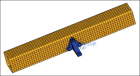
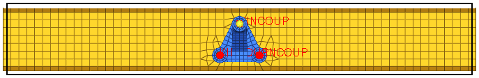
Bracket and cradle assembly
Step 2: Review the card image of one of the elements
| 1. | Open the Card Edit panel by clicking Mesh > Card Edit > Elements from the menu bar. |
| 2. | Verify that the entity selector is set to elems. |
| 3. | Select an element from the bracket (blue elements). |
| 4. | In the panel area, click edit. The card image for the element opens, and displays the element type (either C3D6 or C3D8) and the ELSET name as bracket. |
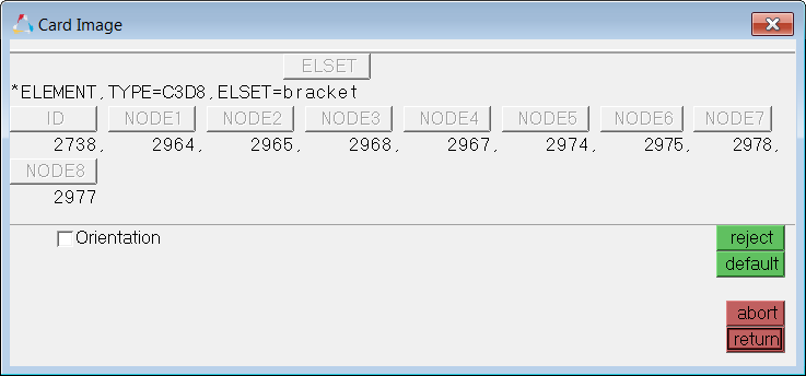
| 5. | Click return to close the card image. |
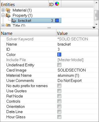
Step 3: View the property card
In this step you will use the Entity Editor to view the sectional properties associated with the elements in the model's components.
| 1. | In the Model browser, Property folder, click bracket. The Entity Editor opens, and displays the bracket’s *SOLID SECTION property and material assignment, which is aluminum. |
Step 4: View the material collector card
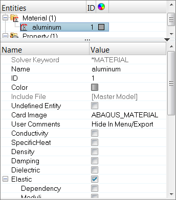
In this step you will use the Entity Editor to review the defined material, aluminum.
| 1. | In the Model browser, Material folder, click aluminum. The Entity Editor opens, and displays the material's card data. |
Review of the model’s content is complete. Next you will complete the model data.
Step 5-6: Create and assign a *MATERIAL for the cradle
In this section, you will create a *MATERIAL with *ELASTIC to define as steel for the ELSET cradle. When you define the sectional property for the cradle component in the next section, the material will already be referenced in the property.
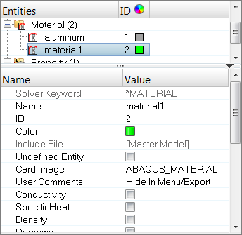
Step 5: Create the material STEEL
| 1. | In the Model browser, right-click and select Create > Material from the context menu. HyperMesh creates and opens a material in the Entity Editor. |
| 3. | Select the Elastic checkbox. |
| Note: | This option creates *ELASTIC. |
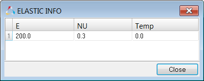
| 4. | In the Data: E row, click  . The ELASTIC INFO dialog opens. . The ELASTIC INFO dialog opens. |
| 5. | For elastic modulus E(1), enter 200. |
| 6. | For Poisson's ration NU(1), enter 0.3. |
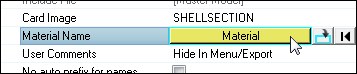
Step 6: Assign the material Steel to the component and define *SHELLSECTION for the cradle property
| 1. | In the Model browser, right-click and select Create > Property from the context menu. HyperMesh creates and opens a property in the Entity Editor. |
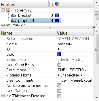
| 2. | For Name, enter cradle. |
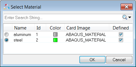
| 3. | For Material Name, click Unspecified >> Material. |
| 4. | In the Select Material dialog, select steel and then click OK. |
| 5. | For Thickness, enter 2.5. |
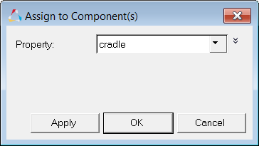
| 6. | In the Model browser, Component folder, right-click on cradle and select Assign from the context menu. |
| 7. | In the Assign to Component(s) dialog, select cradle from the Property list. |
Understanding HyperMesh Entity Configurations and Types
HyperMesh elements and load entities have two identifiers: configuration and type. The entity configuration is a HyperMesh core feature while the entity type is defined by the template. For example, HyperMesh element configurations include rigid, spring, quad4, and hex8. Possible quad4 configuration types in the Standard3D template include S4, S4R, S4R5, among others. Similarly, HyperMesh load configurations include constraints, force, pressure, and temperature. In the HyperMesh Abaqus templates, pressure configuration types include DLOAD, DFLUX, FILM, DECHARGE and Radiate.
Most of the HyperMesh element and load configurations have their own panels. From the 1D, 2D, and 3D pages, use the Elem Types panel. Load types can be chosen directly in the related panels. You can also use the load or element types panels to change the type of load.
Kinematic Constraints in HyperMesh
With the exception of *EQUATION, Abaqus kinematic constraints, such as *KINEMATIC COUPLING and *MPC (BEAM, TIE, LINK, PIN), are rigid (1D) elements in HyperMesh. From the 1D page, use the Rigids panel to create them. Organize them into HyperMesh component collectors. No sectional property or material is needed for these entities. Hence, either organize them into their own component or into a component containing different Abaqus entities.
Steps 7-10: Constrain the bracket to the cradle
In this section, you will create the Abaqus constraint *KINEMATIC COUPLING to simulate a bolt connecting the bracket’s top bolt hole to the cradle. The model already contains two *KINEMATIC COUPLING entities, one at each of the bracket’s bottom bolt holes. They are organized into the bracket component.
Using the steps below, you will start by creating a new component in which you will organize all the *KINEMATIC COUPLING entities. This is not necessary, but is done to organize the data and demonstrate the selection of entities by configuration. This component will contain the *KINEMATIC COUPLING to be created. You will need to select any existing material to avoid creating one that is not needed.
Be sure to use the Elem Types panel to set the type for rigids to KINCOUP. This allows all elements created from the Rigids panel to be of the type *KINEMATIC COUPLING.
Finally, you will create the *KINEMATIC COUPLING using the Rigids panel.
Step 7: Create a new component collector
In this step you will create a new component collector and set the element type rigid to KINCOUP.
| 1. | In the Model browser, right-click and select Create > Component from the context menu. HyperMesh creates and opens a component in the Entity Editor. |
| Note: | This new component is now the current component. HyperMesh will automatically organize any new elements/geometry into this component. |
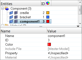
| 2. | For Name, enter connection. |
| 3. | Click the Color icon, and select a color for the component. |
| 4. | Open the Element Type panel by clicking Mesh > Assign > Element Type from the menu bar. |
| 6. | Click rigid = and select KINCOUP. |
Step 8: Create a reference node
In this step you will use the distance panel to create a node at the center of the bolt hole to be the *KINEMATIC COUPLING reference node.
| 1. | Zoom into the top bolt hole as indicated in the following image. |
| 2. | Open the Distance panel by pressing F4. |
| 3. | Go to the three nodes subpanel. |
| 4. | Select the three nodes on the top side of the bolt hole for N1, N2, and N3 as indicated in the image below. |
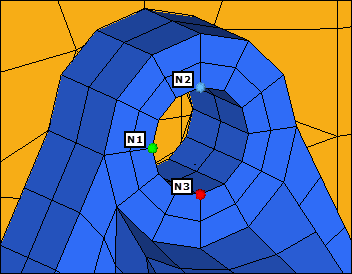
Selecting nodes for circle center
| 5. | Click circle center. HyperMesh creates a node at the center of the selected nodes. |
Step 9: Create a spider-like rigid link
In this step you will use the Rigids panel to create a spider-like rigid link for the *KINEMATIC COUPLING.
| 1. | Open the Rigids panel by clicking Mesh > Create > 1D Elements > Rigids from the menu bar. |
| 2. | Go to the create subpanel. |
| 3. | Constrain the *KINEMATIC COUPLING reference node in all six directions by selecting all of the dof (degree of freedom) checkboxes. |
| 4. | Set the dependent selector to multiple nodes. |
| 5. | Using the independent selector, select the center node that you created in step 8.5. |
| 6. | Using the dependent selector, select all of the nodes on the top side of the bolt hole as indicated in the following image. |
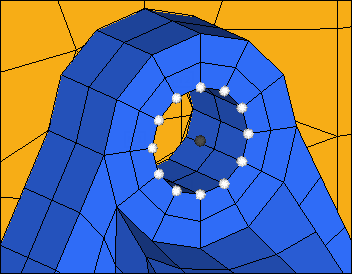
Selecting independent and dependents nodes
| 7. | In the Model browser, Component folder, right-click on bracket and select Hide from the context menu. HyperMesh hides the elements of the bracket component. |
| 8. | Using the dependent selector, select the nodes around the hole in the cradle as indicated in the following image. |
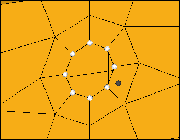
Selecting dependent nodes from the cradle
| 9. | Click create. HyperMesh creates the *KINEMATIC_COUPLING. |
| 10. | In the Model browser, Component folder, right-click on bracket and select Show from the context menu. HyperMesh displays the elements from the bracket component. |
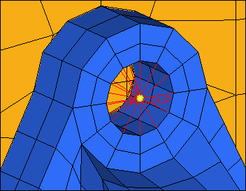
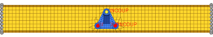
Kinematic coupling
| 11. | Click return. The *KINEMATIC COUPLING is now created and organized into the connection component. |
Step 10: Move the *KINEMATIC COUPLING entities
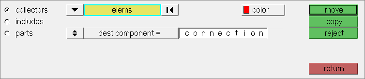
In this step you will move all of the *KINEMATIC COUPLING entities into the connection component using the organize panel.
| 1. | Open the Organize panel by clicking Mesh > Organize > Elements > To Component from the menu bar. |
| 2. | Click elems >> by config. |
| 3. | Click config =, and then select rigidlink. |
| 4. | Click type =, and then select KINCOUP. |
| 5. | Switch the displayed/all toggle to all. |
| 6. | Click select entities. HyperMesh selects all of the rigid links in the model. |
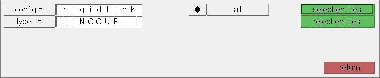
| 7. | Click dest component =, and then select connection. |
| 8. | Click move. HyperMesh moves all of the rigid links to the connection component. |
| 9. | Click return. All the *KINEMATIC COUPLING entities are now organized into the connection component. Model data definition is complete. |
Using Step Manager for initial conditions
In HyperMesh, you can use the Step Manager tool to create, edit, review, re-order, and delete Abaqus initial conditions and steps.
Open the Step Manager by clicking Tools > Load Step Browser from the menu bar.
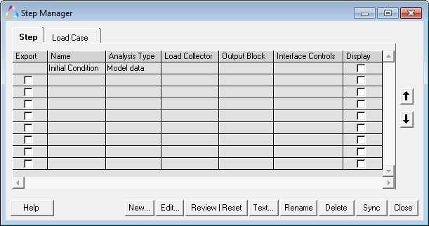
The Step Manager has a default step named Initial Condition. This step is used to create boundary conditions and loads (initial conditions) in the model data portion of the Abaqus input file.
When you edit the Initial Condition step, the Load Step: Initial Condition dialog opens. You can only select valid boundary conditions and load types for model data in this dialog..
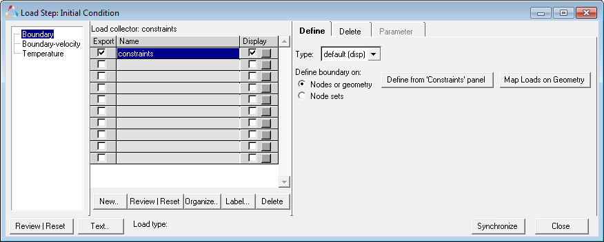
Initial Condition Dialog
Use this dialog from left to right by:
| • | Selecting a load step type from the list (left column) |
| • | Creating a load collector (center area) |
| • | Creating the loads using the menu area (right side) |
Step 11: Define *BOUNDARY
In this step you will create constraints at the cradle’s ends using the Step Manager. You will then define the constraints as model data, not history data, by editing the Step Manager’s default step named Initial Condition. For this step, you will create a load collector and then create the constraints.
| 1. | Open the Load Step Manager by clicking Tools > Load Step Browser from the menu bar. |
| 2. | In the Step tab, click Initial Condition. |
| 3. | Click Edit to modify the step. |
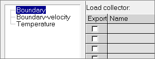
| 4. | In the Load Step: Initial Condition dialog, select Boundary from the first pane. |
| Note: | This specifies the type of initial condition you want to create. |
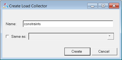
| 5. | Click New to create a new load collector. |
| 6. | In the Create Load Collector dialog, Name field, enter constraints. |
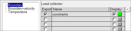
| 8. | In the Load collector table, select the Display checkbox for the the constraints load collector. |
| 9. | Optional. Next to the Display checkbox, click the Color box and select a color for the load collector. |
| 10. | In the Load collector table, click constraints. The collector becomes active, and new tabs appear on the right side of the dialog. |
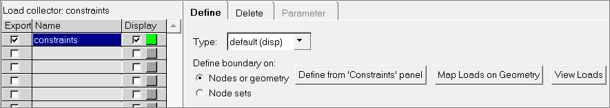
| 11. | In the Define tab, set Type to default (disp). |
| 12. | Click Define from 'Constraints' panel. The Constraints panel opens. |
| 13. | From the Standard Views toolbar, click  . . |
| 14. | In the Constraints panel, click nodes >> by window. |
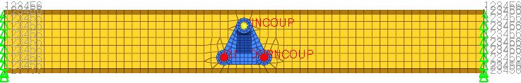
| 15. | With the exception of the nodes at the ends of the cradle, draw a rectangle around all of the displayed nodes to select them as shown below. |
| 16. | Select the exterior checkbox, and then click select entities. HyperMesh selects all of the nodes outside the window you drew. |
| 17. | Constrain the selected nodes in all six directions by selecting all of the dof (degree of freedom) checkboxes. |
| 18. | Click Create. HyperMesh creates the constraints. |
| 19. | Click return to go back to the Step Manager. |
| 20. | Exit the Initial Condition step and return to the Step Manager by clicking close. |
Define the history data
The history data portion of the Abaqus input file defines the sequence of events for the simulation. The loading history is divided into a series of steps. Each step contains the type of simulation, loads, constraints, output requests, and contacts (for Abaqus Explicit). The Abaqus *STEP option marks the start of a step, while the *END STEP option marks the end.
In the Step Manager you can create, review, edit, delete, and re-order the Abaqus steps. In the Step Manager, loads are organized into load collectors and output requests are organized into HyperMesh output blocks.
Step 12: Define the Abaqus step
For this analysis, you will be looking at the linear static response of the cradle and bracket assembly to a 100 kN load applied on the bracket, with the cradle’s ends fully constrained. This is a single event, therefore only one Abaqus step is needed. In this step you will use the Step Manager to define the step's title, heading, parameters, and the analysis procedure, and then apply a concentrated force (*CLOAD) on the bracket’s arm.
| 1. | In the Step Manager, Step tab, click New. |
| 2. | In the Create New Step dialog, Name field, enter step1. |
| 3. | Click Create. HyperMesh creates a new step. |
| 4. | In the first pane, click Title. Additional options display, from which you can define the step's title. |
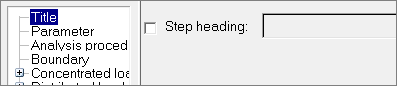
| 5. | Select the Step heading checkbox, then enter 100kN load. |
| 7. | In the first pane, click Parameter. |
| 8. | Write the step’s name to the Abaqus input file by selecting the Name checkbox. |
| 9. | Set the analysis for small-scale, linear deformations by selecting the Perturbation checkbox. |
| 11. | In the first pane, click Analysis procedure. |
| 12. | Set Analysis type to static. |
| 14. | Click Text to review what has been defined so far for the step. |
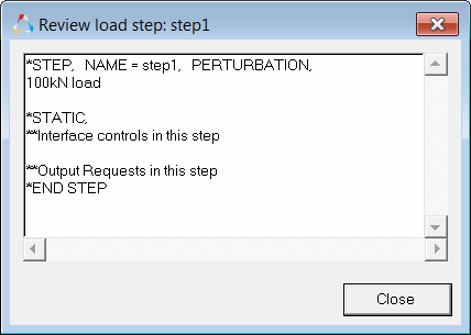
| 15. | When you are finished reviewing the contents of the window, click Close. |
| 16. | In the first pane, expand Concentrated loads, and click CLOAD-Force. |
| 17. | Click New to create a new load collector. |
| 18. | In the Create Load Collector dialog, Name field, enter force. |
| 20. | Optional. Next to the Display checkbox, click the Color box and select a color for the load collector. |
| 21. | In the Load collector table, click force. The collector becomes active, and new tabs appear on the right side of the dialog for the selected load type (CLOAD-Force). |
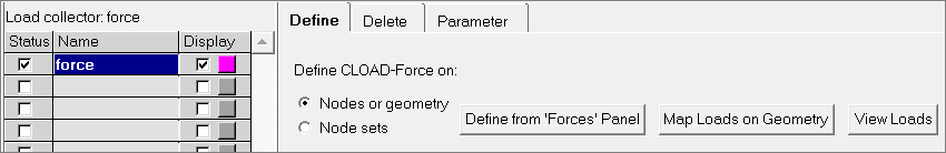
| 22. | In the Define tab, click Define from ‘Forces’ Panel. HyperMesh opens the Forces panel, from which you can create a CLOAD. |
| 23. | Select the central node on the top side of the bracket’s arm as indicated in the following image. |
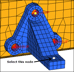
Node for CLOAD
| 24. | In the magnitude = field, enter –100. |
| 25. | Leave the system selector set to global system. |
| 26. | Set the orientation selector to z-axis for the force’s direction vector. |
| 27. | Click create. HyperMesh creates the force. |
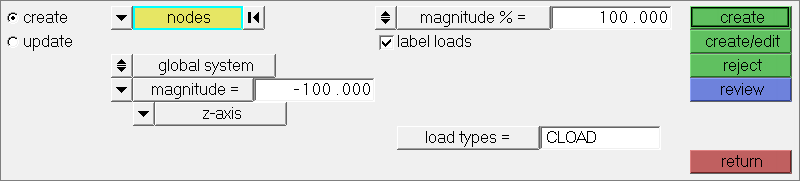
| 28. | Click return to go back to the Step Manager. |
Step 13: Specify output requests for the step
In this step you will use the Step Manager to specify displacement and stress results to output to the .odb and .fil results files for step1. You will then export the model to an .inp file.
| 1. | In the first pane of the Load Step dialog, expand Output request, and click ODB file. |
| 2. | Click New to create a new output block. |
| 3. | In the Create Output block dialog, Name field, enter step1_output. |
| 5. | In the Output block table, click step1_output. |
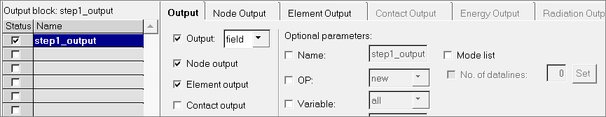
| 6. | From the Output tab, select the Output checkbox. |
| 7. | Leave Output set to field. |
| 8. | Select the Node output and Element output checkboxes. |
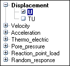
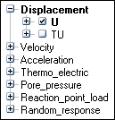
| 9. | Click the Node Output tab. From this tab you can specify the nodal displacement output for the .odb file |
| 10. | From the list of output options, expand Displacement, and select the U checkbox. |
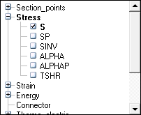
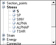
| 12. | Click the Element Output tab. From this tab you can specify elemental stress output for the .odb file. |
| 13. | From the list of output options, expand Stress, and select the S checkbox. |
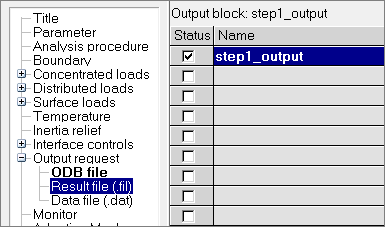
| 15. | In the first pane of the Load Step dialog, expand Output request, and select Result file (.fil). |
| Note: | The output block, step1_output, is still highlighted (active) in the Output block table. |
| 16. | In the Define tab, select the Node file and Element file checkboxes. |
| 17. | Click the Node File tab. From this tab you can specify nodal displacement output for the .fil file. |
| 18. | From the list of output options, expand Displacement, and select the U checkbox. |
| 20. | Click the Element File tab. From this tab you can specify the elemental stress output for the .fil file. |
| 21. | Select the Position checkbox. |
| 22. | Set Position to averaged at nodes. |
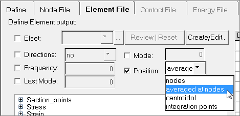
| 23. | From the list of output options, expand Stress, and select the S checkbox. |
| 25. | Click Close to exit the Load Step dialog. |
| 26. | Click Close to exit the Step Manager. You are now finished defining the step. |
Step 14: Export the model
| 1. | From the menu bar, click File > Export > Solver Deck. The Export - Solver Deck tab opens. |
| 2. | In the File field, navigate to your working directory and save the file as bracket_cradle_complete.inp. |
| 3. | Click Export. You can now submit the .inp file to Abaqus for analysis. |
This concludes this tutorial. You may discard this HyperMesh model or save it to your working directory for your reference.
In this tutorial, you were introduced to some of the concepts that govern the HyperMesh interface to Abaqus. You also used the Step Manager to do basic modeling in terms of Abaqus, such as defining boundary conditions, output requests, and steps.
For additional tools and techniques, refer to the tutorial HM-4350: Pre-Processing for Crashing Tubes Analysis using Abaqus.
See Also:
HyperMesh Tutorials


