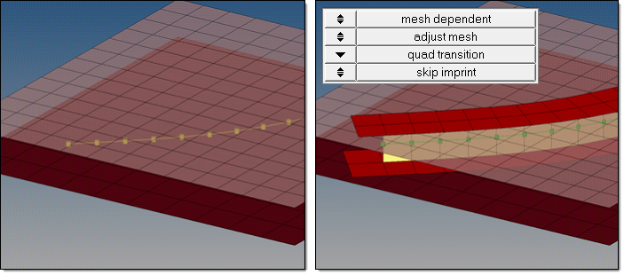
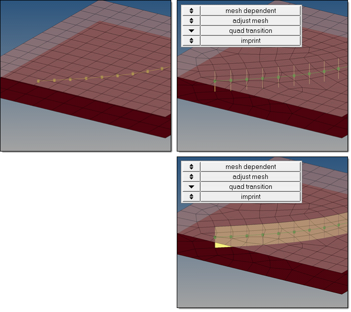
HyperMesh and BatchMesher

Seam Panel Realization Methods

Seam Panel Realization Methods

Previous topic Next topic Expand/collapse all hidden text  

Seam Panel Realization Methods

Previous topic Next topic JavaScript is required for expanding text JavaScript is required for the print function  

The following flow chart outlines a four-stage process used to select the best routine for seam realization.

connector_realization_seam

In stage 1, select the type of realization.

mesh independent

Use for realizations which do not need a node connection and the connection is primarily defined via a solver-specific card, such as LLINKs for Pamcrash.

mesh dependent

Use for all other cases.


In stage 2, if mesh dependent is selected, you must decide next whether or not to adjust the mesh or the realization.

Adjust mesh

Projection is done in a perpendicular way, and the mesh has to be adapted to the projection points.

Adjust realization

The mesh will not be modified, at the expense of non-normal or incomplete realizations. Many realization types are defined with head elements attached to body elements. In the case of these realization types, the head elements realize the connection without modifying the mesh, and the body elements are created in a normal direction.


In stage 3, decide how the adjustments should take place.

Adjust mesh

Sub-options include: quad transition and remesh.

Adjust realizations

Sub-options include: find nearest nodes, project and find nodes, and ensure projection.


In stage 4, decide whether or not the imprint should be skipped for quad transition.


Seam Realization Methods

The following examples illustrate and explain the different options for seam realization methods.

hmtoggle_arrow1Mesh independent

The mesh independent option is normally used for solver-specific realization types. Then a post script is performed during realization to define the solver specific connection. That is, for the Pamcrash LLINK all necessary solver specific cards are created along with the realization.

connector_realization_seam_meshindependent


hmtoggle_arrow1Mesh dependent – adjust mesh – quad transition - imprint

Quad Transition

Creates perfectly shaped quad elements around the projection line. The quad size is determined by the average mesh size. From one projection point to the next, exactly one pair of elements is created. You can also use this option to create seams from quad elements, and realize the connections to the links through perfectly modeled t-edges.

For seam quad transition, the allow snapping option is automatically activated. This prevents the creation of elements that are too small, and ensures that the geometry is not modified too much.

Free edges and features with an angle greater than 25° are always taken into account. If smaller feature angles should be considered, the feature angle in the mesh options menu has to be decreased. Feature angles smaller than 5° will not be considered at all.

By default, snapping is allowed by a distance of one third of the quad pattern element size. In the case of a predefined quad pattern element size of 10.0, the outer nodes can snap to features in a distance of 3.3. The algorithm also tries to snap all three nodes of a quad pattern or none.


Imprint

When creating mesh-dependent realizations with quad transitions, the quad transition meshes can overlap and disturb each other if more than one set of connectors is created too close to each other. Imprint reconciles such transitions with each other and modifies the underlying mesh to match the results. This creates a final result that is seamless and properly meshed.

To enable smaller imprint conflicts to be automatically resolved when connectors are realized, the resolve conflicting imprints option is activated by default. Overlapping elements are released, and a normal remesh of that area is performed as long as the overlapping area is smaller than half the regular quad transition element size. Larger conflicts may require a manual imprint. See mesh edit - imprint for connectors for more details.

The size of the imprint can be determined using the pitch size (use pitch size to imprint) or using the average size of the underlying mesh (use avg. mesh size to imprint). If you want to define a specific imprint size, select size to imprint.

connector_realization_seam_meshdependent_adjustmesh_quad transition_imprint


hmtoggle_arrow1Mesh dependent – adjust mesh – quad transition – skip imprint

Quad Transition

Creates perfectly shaped quad elements around the projection line. The quad size is determined by the average mesh size. From one projection point to the next, exactly one pair of elements is created. You can also use this option to create seams from quad elements, and realize the connections to the links through perfectly modeled t-edges.

For seam quad transition, the allow snapping option is automatically activated. This prevents the creation of elements that are too small, and ensures that the geometry is not modified too much.

Free edges and features with an angle greater than 25° are always taken into account. If smaller feature angles should be considered, the feature angle in the mesh options menu has to be decreased. Feature angles smaller than 5° will not be considered at all.

By default, snapping is allowed by a distance of one third of the quad pattern element size. In the case of a predefined quad pattern element size of 10.0, the outer nodes can snap to features in a distance of 3.3. The algorithm also tries to snap all three nodes of a quad pattern or none.


Skip Imprint

Prevents the last step of quad transition from being performed. The component ^conn_imprint is created instead, which contains the element pattern. These elements can be modified and manually imprinted later using the Connector Imprint panel.

Skip imprint enables you to realize such mesh-dependent realizations, even in very complex areas of the model where the automatic imprint fails because of issues such as conflicting seams.

The size of the imprint can be determined using the pitch size (use pitch size to imprint) or using the average size of the underlying mesh (use avg. mesh size to imprint). If you want to define a specific imprint size, select size to imprint.

connector_realization_seam_meshdependent_adjustmesh_quad transition_skipimprint


hmtoggle_arrow1Mesh dependent – adjust mesh – remesh

Remesh uses snap and split capabilities to connect 1D welds to the links in the position of the projection points. In the case of a quad realization, remesh looks for a correct t-edge.

connector_realization_seam_meshdependent_adjustmesh_remesh


hmtoggle_arrow1Mesh dependent – adjust realization – find nearest nodes

Searches for the nearest nodes within the given tolerance, making it possible to connect t-joints and similar areas. This option is very useful in situations where the connectors are not positioned perfectly. These realizations are allowed to be non-normal. Find nearest nodes does not do any projection.

Note:If the connector points are close to each other and two of these points find the same closest nodes the connector fails.

connector_realization_seam_meshdependent_adjustrealization_findnearest


hmtoggle_arrow1Mesh dependent – adjust realization – project and find nodes

Produces the same exact result as find nearest node because a non-normal projection for seams is always allowed. Principally, project and find nodes requires a valid projection onto the link entities in the first step. In the second step, the nodes closest to the projection points will be used for the connection. If the projection (connector tolerance) is not possible, the realization fails.

Note:The realization fails when the connector points are close to each other, and two of these points find the same nodes.

connector_realization_seam_meshdependent_adjustrealization_project


hmtoggle_arrow1Mesh dependent – adjust realization – ensure projection

When using this option, the minimum condition for the realization is a possible normal projection. The realization will be performed in the direction from one projection point to the next. If the projection point is coincident with a shell node they will be equivalenced.

Note:Ensure projection can lead to incompletely defined connections from a solver perspective unless the connector positions are not aligned to the mesh. The advantage of this projection method is the exact determination of the projection points.

The ensure projection option is comparable to the older use shell node option, which is no longer available.

connector_realization_seam_meshdependent_adjustrealization_ensureprojection


See Also:

Connector Panels

connectors module