In this tutorial, you will learn how to use the TetraMesh Process Manager to:
| • | Import geometry or a HyperMesh File |
| • | Organize the model (holes and features) |
| • | Establish mesh size and pattern for the organized geometry |
The Process Manager contains a step-by-step checklist of procedures that allow you to quickly organize and tetramesh a geometric model. Each step is formatted in a hierarchical list that provides the order in which the process must be performed. Specialized tools are also provided at each step to simplify the process. You can perform these steps manually, but it is generally faster to perform them in the Tetramesh Process Manager.
Model Files
This exercise uses the tetmesh_pm.hm file, which can be found in the hm.zip file. Copy the file(s) from this directory to your working directory.
Exercise
Step 1: Initiate the Process Manager.
| 1. | Start a new session in the TetraMesh Process Manager by clicking Mesh > Create > TetraMesh Process > Create New from the menu bar. |
| 2. | In the Create New Session dialog, enter a name for the session in the New Session Name field. |
| Note: | Creating a session name and saving the session allows you to stop the process before completion and then load it again at a later time, picking up the process at the point it was left off. |
| 3. | In the Working Folder field, navigate to the location of your working directory. |
| 4. | Click Create. The Process Manager opens in the tab area. |
Step 2: Import geometry.
At this point, the TetraMesh Process Manger automatically assembles the TetraMesh process flow. The first step, Geometry Import, is highlighted in the tab area, and the panel area has been configured with specific panels for aiding the Tetramesh Process Manager template. If you need to access standard HyperMesh panels, undock the Process Manager panels to a separate dialog by clicking  in the panel area. To re-dock the Process Manager panels, click
  in the Process Manager dialog.
| 1. | In the panel area, set Import Type to HM Model. |
| 2. | In the Import Filename field, open the file tetmesh_pm.hm. |
| 3. | Click Import. Hypermesh imports the model. |
| Note: | A green checkmark appears next to the Geometry Import step in the Process Manager tab, which indicates that the step is complete. |
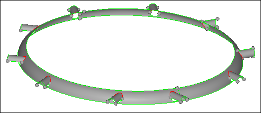
Step 3: Clean up the geometry.
| 1. | On the Visualization toolbar, select  from the list of geometry color modes, and click from the list of geometry color modes, and click  to shade the model's geometry and surface edges. to shade the model's geometry and surface edges. |
| 2. | In the panel area, select the Edge Tools tab. |
| 3. | Click Isolate. HyperMesh isolates the surfaces with free edges on them. |
Isolated Surfaces with free edges.
| 4. | Select the Free Edges tab. |
| 5. | Click Equivalence. HyperMesh fixes all of the free edges. |
| Tip: | If this did not correct all of the free edges, increase the Tolerance value until all of the free edges are equivalenced. |
| 6. | Select the Edge Tools tab. |
| 7. | Click Isolate. A dialog appears with a message that reads, "No edges found..." |
| Note: | This confirms that all of the edges have been fixed. |
| 8. | Click Display All. HyperMesh displays the entire model. |
Step 4: Organize and Clean up holes.
In the Organize and Cleanup Holes step, you will organize the surfaces that form holes in the model. The TetraMesh Process Manager can automatically sort and organize holes into separate component collectors based upon their diameter. This will allow you to specify a mesh type, circumference element count, and longitudinal element size for different hole groups.
| 1. | In the Hole Parameters Table, D< column, enter 5 in the first row and 10 in the second row. |
| Note: | This will organize the holes into two collectors that will include holes ranging from 0 - 5 units and 5 - 10 units collectively. |
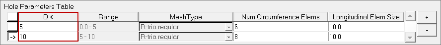
| 2. | Click Auto Organize. HyperMesh organizes all of the holes in the model less than 10 units into two component collectors, each with a different color. |
| 3. | From the Model browser, expand the Components folder. |
| Note: | Two new component collectors, with the name solidholes followed by the numerical average of the diameter range of the holes, are created. |
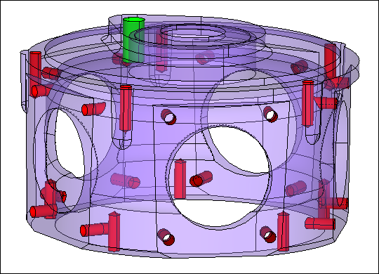
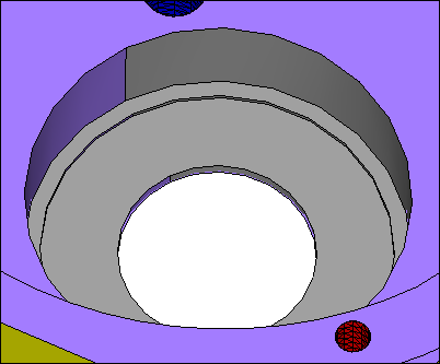
Transparent view of model showing all holes and bores organized
| 4. | In the Hole Parameters Table, Num Circumference Elems column, enter 12 in each row. |
| Note: | The Num Circumference Elems field governs the number of elements that will be meshed around the hole. |
| 5. | In the Longitudinal Elem Size column, enter 1 in each row. |
| Note: | The Longitudinal Elem Size field dictates the unit size of the elements through the length of the hole. |
Step 5: Mesh holes.
| 1. | In the Hole Parameters Table, Mesh Type column, select R-tria regular in each row. |
| 2. | Click Mesh All. HyperMesh creates a perfectly straight tria mesh down the length of the holes with no twisting. |
Step 6: Organize and clean up features.
In the Organize and Cleanup Features step, you will highlight and organize features that require specific mesh controls beyond the overall mesh pattern that will be applied to the remainder of the part in a later step. You will use the organizational tool to place the required surfaces into their own collector or collectors, and set a mesh size and pattern requirements for each.
| 1. | In the panel area, click  . . |
| 2. | In the Define New dialog, enter Faces in the text field. |
| 4. | Select all five of the flat faces around the circumference of the part as indicated in the following image. |
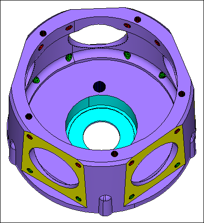
Isolated view of the five flat faces
| 5. | Click proceed. The Organize panel opens with the surfaces pre-selected and ready to move into a new component called grp_Faces. |
| 8. | Click . |
| 9. | In the Define New dialog, enter TopHole in the text field. |
| 11. | Rotate the model so you are looking at it from underneath into the center. |
| 12. | Select the five surfaces that are shaded gray, as indicated the following image. |
| Note: | You only need to select one of the two surfaces that make up a cylinder; when you click proceed HyperMesh automatically selects the other surfaces. |
| 14. | In the Organize panel, click move. |
| Note: | Your model should look similar to the following image, with the faces in one collector and the top hole in another. Your colors may vary slightly. |
Step 7: Organize and clean up filets.
Often a better mesh can be achieved if your fillets are split down the center. In the Organize and Cleanup Fillets step, you will split your fillets based on a minimum and maximum radius criteria.
| 2. | Select the part in an area that has not been organized into a new component so that the large purple part is selected. |
| 4. | Verify that the Min Radius is 0, and the Max Radius is 5. |
| 5. | Select the Suppress fillet tangent edges checkbox. |
| Note: | Many of the fillets now have an edge running down the center and the original edges are suppressed. |
Step 8: Mesh features.
In the Mesh Features step, you will mesh the features that you organized in step 6. The panel area will contain a table with your organized features. In the table, you will be able to select a mesh type and specify an element size for each feature.
| 1. | In the Feature Parameters Table, set the Mesh Type for Faces to trias. |
| 2. | For TopHole, set the Mesh Type to R-tria union jack. |
| 3. | For both features, enter 0.5 in the Elem Size field. |
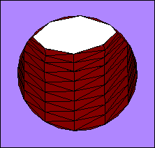
| Note: | Notice the distinctive Union Jack mesh pattern ( ) in the top hole area and the connectivity of the mesh to the previously meshed holes. ) in the top hole area and the connectivity of the mesh to the previously meshed holes. |
Step 9: Organize and clean up.
In the Organize and Cleanup step, you will organize and clean up the remaining portion of the model that will then fall under the global meshing parameters. As the remaining surfaces are already in the component you wish them to be in, there is no need for further organization.
Step 10: Mesh/remesh.
In the Mesh/Remesh step, you will globally mesh the remaining model. You can select a mesh type and specify an element size for all of the components that remain unmeshed.
| 1. | In the panel area, enter 1 in the Element Size field. |
| 2. | Set Mesh Type to trias. |
Step 11: Clean up elements.
At this point the model should be entirely surface meshed. Proper adherence to the previous steps ensures a surface mesh that is properly connected and controlled by the previously entered values. In the Element Cleanup step, you will verify a proper mesh and clean up any issues that are found.
| 1. | In the panel area, click Components. |
| 3. | Select all of the components. |
| 6. | Leave all of the values at their default (Min Size = 0.25, Max FeatureAngle = 60.0, and Normals Angle = 150.0). |
| 7. | Click AutoCleanup. A dialog appears with a message that reads, "Cleanup process performed on 32 failed elements. No failed elements remain." |
| Note: | This confirms that all failed edges have been fixed and there are no further errors in the model. |
| 8. | Optional: Use the Manual tab to manually check the model for free edges and t-junctions, and fix any that are found. There is also an option to display normals. Use these options to find and fix any errors. |
| Note: | The Tetramesh Process Manager automatically places any elements that fail the AutoCleanup procedure in the user mark. This allows for easy retrieval of problem elements. You can employ the tools from the standard HyperMesh panels to fix these remaining elements. |
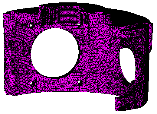
Step 12: Tetra mesh.
Tetra Meshing is the final step in the TetraMesh Process Manager Template. During this step, the model will be Tetra meshed. The Process Manager automatically opens the TetraMesh panel and pre-selects all of the float and fixed elements.
| 1. | Under Float trias/quads to tetra mesh, click elems. HyperMesh selects the surface elements under the general mesh selection option. |
| Note: | This option defines the selected elements as “floatable”, meaning that the diagonals of the underlying tetra elements can be flipped from the generated shell elements if HyperMesh determines a better element quality will result. |
| 2. | Under Fixed trias/quads to tetra mesh, click elems. HyperMesh selects the elements that represent the interior of holes and bores. |
| Note: | The option defines the selected elements as “fixed”, meaning HyperMesh will always adhere to the shell mesh pattern when generating the tetra elements. |
| 4. | From the Model browser, expand the Components folder. |
| 5. | Right-click on tetmesh, and select Isolate Only from the context menu. Hypermesh displays the tetra mesh. |
| 6. | Open the Mask panel by clicking  on the Display toolbar. on the Display toolbar. |
| 7. | Press Shift + left-click, and then drag a box to include roughly half of the model. |
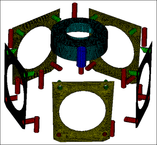
| Note: | Your tetra mesh should look similar to the following image. |
Step 13 (Optional): Save your work.
You can now save your model if you wish.
| 1. | From the menu bar, click File > Save > Model. |
See Also:
HyperMesh Tutorials


