| 1. | Click Add Output Response. |
| 2. | In the HyperStudy - Add dialog, add three output responses. |
| 3. | In the Expression column of Response 1, click  . . |
| 4. | In the Expression Builder, click the File Sources tab. |
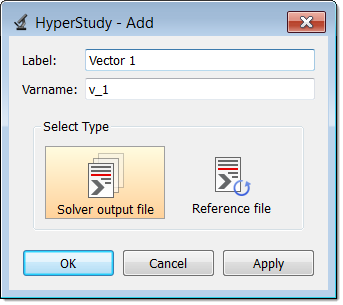
| 6. | In the HyperStudy - Add dialog, add one solver output file. |
| 7. | In the File column of Vector 1, click . |
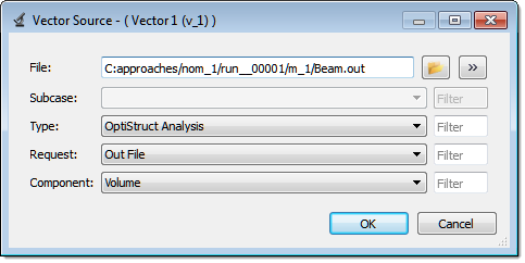
| 8. | In the Vector Source dialog, File field, navigate to the approaches/nom_1/run__00001/m_1 directory and open the Beam.out file. |
| 9. | From the Type, Request, and Component fields, select the options indicated in the image below. |
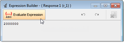
| 11. | Click Insert Varname. The expression v_1[0] appears in the Evaluate Expression field. |
| Note: | Because there is only a single value in this vector, [0] is inserted after v_1, thereby choosing the first (and only) entry in the vector. |
| 12. | Click Evaluate Expression. The expression v_1[0] changes to 2000000. |
| 14. | In the Expression column of Response 2, click . |
| 15. | In the Expression Builder, click the ASCII Extracts tab. |
| 16. | Click Add Extract Source. |
| 17. | In the HyperStudy - Add dialog, add one extract source. |
| 18. | In the File Path column of FileParser1, click . |
| 19. | In the Extract file dialog, navigate to the approaches/nom_1/run__00001/m_1 directory and open the Beam.out file. |
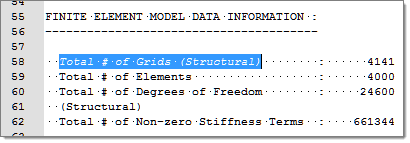
| 20. | Select the Keyword checkbox and enter Total # of Grids (Structural). |
| 21. | Click Next. The phrase Total # of Grids (Structural) is highlighted. |
| 22. | Right-click on the highlighted fields and select Keyword from the context menu. The keyword Total # of Grids (Structural) is created. |
| 23. | Highlight the value 4141 to the right of Total # of Grids (Structural). |
| 24. | Right-click on the highlighted fields and select Value from the context menu. This number gives you the total number of grids. |
| Note: | You will need this number because the number of grids will change for each design as they are re-meshed, therefore the index for searching the maximum x-displacement among all the grids. |
| 26. | Click Insert Varname. The expression f_1[0] appears in the Evaluate Expression field. |
| Note: | Because there is only a single value in this vector, [0] is inserted after f_1, thereby choosing the first (and only) entry in the vector. |
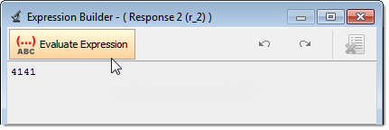
| 27. | Click Evaluate Expression. The expression f_1[0] changes to 4141. |
| 29. | In the Expression column of Response 3, click . |
| 30. | In the Expression Builder, click the Functions tab. |
| 31. | From the list of functions, select max. |
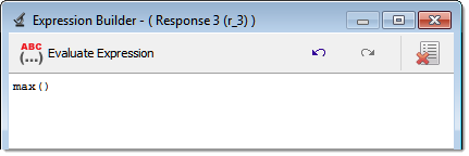
| 32. | Click Insert Varname. The function max() appears in the Evaluate Expression field. |
| 33. | From the list of functions, select ResVector. |
| 35. | In the resvector - Builder dialog, File field, navigate to the approaches/nom_1/run__00001/m_1 directory and open the Beam.h3d file. |
| 36. | From the Subcase, Type, Request, and Component fields, select the options indicated in the image below. |
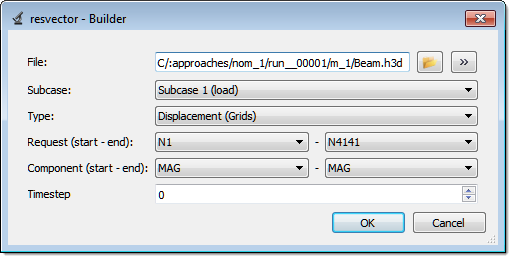
| 37. | Click OK. The expression changes to max(resvector(getenv("HST_APPROACH_RUN_PATH") + "/m_1/Beam.h3d",1,0,4140,3,3,0,0)). |
| 38. | In the expression, replace 4140 with r_2-1. |
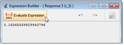
| 39. | Click Evaluate Expression. The expression max(resvector(getenv("HST_APPROACH_RUN_PATH") + "/m_1/Beam.h3d",1,0,r_2-1,3,3,0,0)) changes to 0.16365569829940796. |
|