In this tutorial, you will learn how to:
| • | Import and edit an image |
| • | Overlay the image on top of an animation file and play the animation |
| • | Import a video as a 2D image |
| • | Overlay the video with an animation file and play the animation |
| • | Align a video using multiple point alignment or camera properties |
| • | Import a video as a 3D image |
| • | Rotate and animate the video and animation file together |
Tools
To access the Image Plane panel:
| • | Click the Image Plane panel button on the Annotations toolbar  . . |
OR
| • | From the Results Browser right click and select Create > Image Plane. |
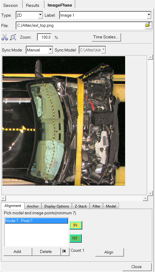
The Image Plane panel allows you to import images and video files to the HyperView animation window. These images and videos can be edited and graphically placed in the animation window. They can also be imported as 2D images or 3D images which can be rotated in the graphics window just like a results file. The videos can be animated and synchronized to an animation file.
Exercise: Using the Image Plane panel
This exercise uses the explorer.h3d file as both the model and the results file.
Step 1: Import and edit an image, then animate the model.
| 1. | Load the explorer.h3d file, located in the animation folder. |
| 2. | Within the Results Browser, expand the Section Cuts folder and click on the  icon next to Section 2. icon next to Section 2. |
The display of the section cut for Section 2 is turned off in the graphics area.
| 3. | Click the Image Plane panel button  on the Annotations toolbar. on the Annotations toolbar. |
| 4. | Use the drop-down menu to set the Type: to 2D. |
| 5. | Enter Altair for the Label. |
| 6. | Click on the Open File icon  next to File and select the file altair.png. next to File and select the file altair.png. |
The file is imported into the animation window. Notice the size of the image in the animation window.
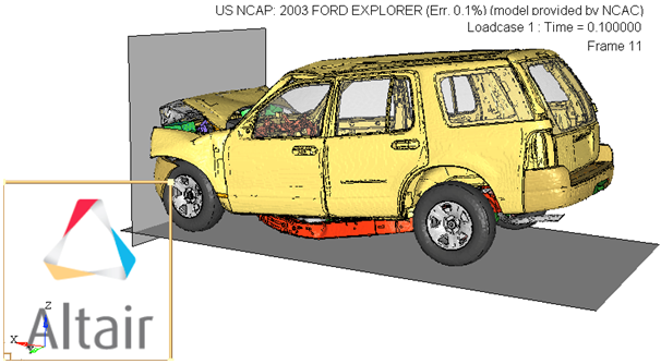
| 7. | To resize the image, click on any of the corners of the graphical manipulator and drag to the new desired location. Resize the image as shown below: |
| 8. | To move the image, use the graphical manipulator in the lower left corner of the image. Click on the horizontal axis to move the image horizontally, and click on the vertical axis to move vertically. Center the image in the graphics window as shown below: |
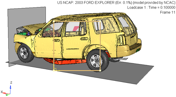
You can also place the image at the center of the animation window by clicking on the Anchor tab in the Image Plane panel and selecting the Center icon,  .
.
| 9. | Notice how the image cannot be seen because it lies under the animation. To bring the image to the front, click on the Z-Stack tab in the Image Plane panel and with the image label (Altair) highlighted, click the up arrow,  . . |
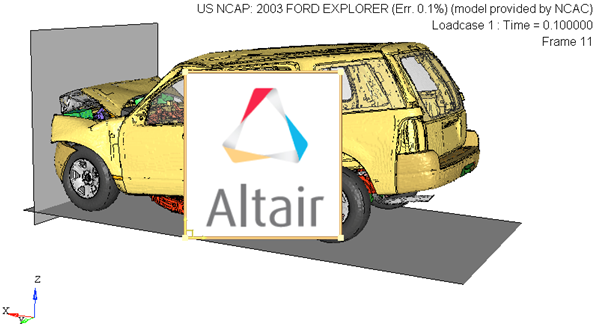
| 10. | Click on the Filter tab. Using this tab, the color white will be removed from the image so that is has a transparent background. |
| - | Set the Type to ColorAlpha. |
| - | Set the Pixel mapping to Linear2. |
| - | Set the Mode to Greaterthan. |
| - | Click on the Color option and pick the gray color (just below white) from the color palette. |
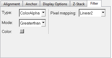
These settings remove the color white from the image.
| 11. | Close the Image Plane panel by clicking on the X at the top of the tab. |
Notice how the model animates with the image placed on top of the model.
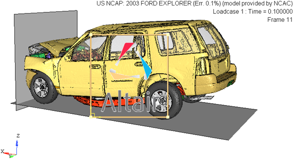
Step 2: Import a video and animate with model.
| 1. | In the Results Browser, expand the Image Planes folder. |
Notice that there is the image plane named Altair that we created in the previous step.
| 2. | Right-click in the Results Browser and select Create > Image Plane. |
| 4. | Enter Explorer for the Label. |
| 5. | Click on the Open File icon (next to File), select the file 06Explorer-f.avi, and click Open. |
| 6. | Select the XZ Right Plane View  to align the h3d model and the avi file in the same plane. to align the h3d model and the avi file in the same plane. |
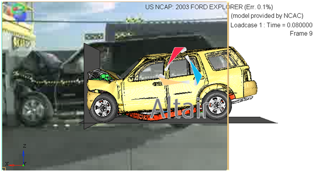
| 7. | Resize and move the image in the same manner as the altair.png file. Resize and move the image to match the size and location of the model. |
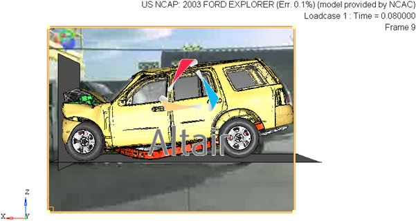
Notice how the model animates with both the image placed on top of the model and the video in the background.
Step 3: Align a video using multiple point alignment or by entering camera properties.
| 1. | From the Image Plane panel, click on the Alignment sub-tab. This sub-tab allows you to pick points on the image (in the image plane tab) and corresponding nodes on the model (in the graphics window). |
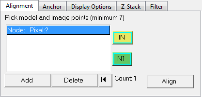
The points on the image and the corresponding nodes on the model should be as close and accurate as possible, in order to optimize the alignment and scaling. A minimum of seven points/nodes are required, however for this exercise we will select a total of nine points/nodes.
| Note | To enable the easy picking of nodes on the model, please make the image in the graphics window completely transparent by using the slider bar in the Display Options tab (sliding to High), or turn off the display of the Image plane from the Results browser tab. You can also adjust the color of the model, if necessary. |
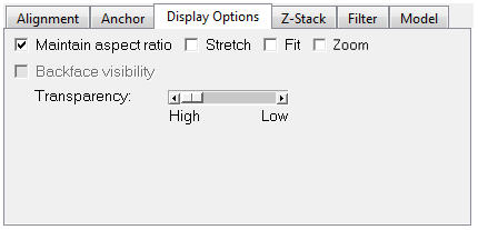
| 2. | A set of nine node-point pairs that provided a good alignment with a very low error value are shown in the images below. For the purpose of this exercise, please try and select your points and nodes as closely as possible to those on the images: |
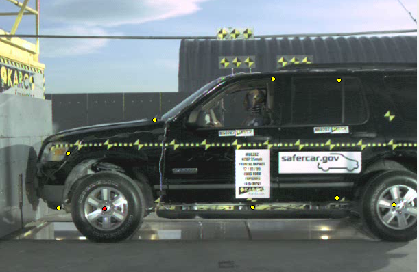
Image plane with 9 points selected
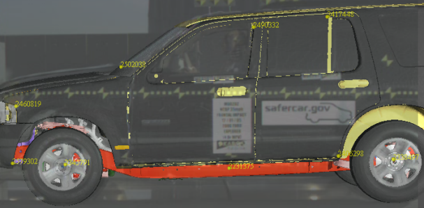
Model with 9 nodes selected
| - | Select the middle of the front wheel as the first point on the image (Pixel: 184 172). |
| - | Next, select the middle of the front wheel as the first node on the model (Node: #2345791). |
The Alignment tab is populated with the first point and node pair.
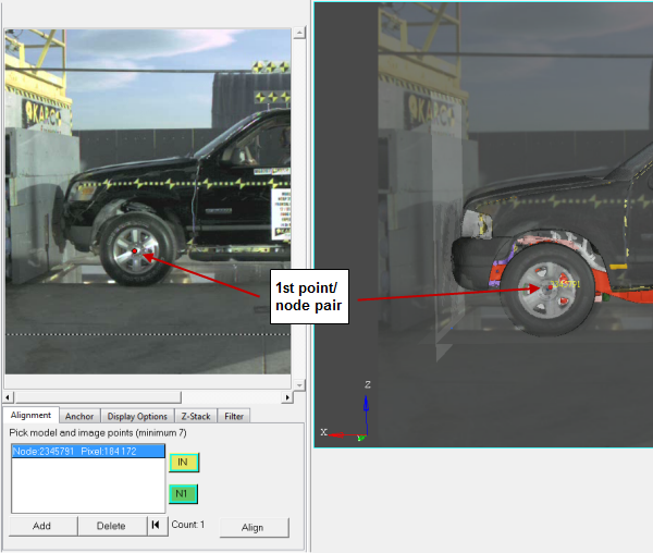
| - | Click the Add button and pick the second image point/node pair (Pixel: 606 178 Node: 2338497). |
| - | Click the Add button again and continue this process to select the seven remaining point/node pairs (see the table below): |
Pixel: 131 253
|
Node: 2460819
|
Pixel: 117 173
|
Node: 2579302
|
Pixel: 430 362
|
Node: 2490332
|
Pixel: 257 302
|
Node: 2502038
|
Pixel: 526 360
|
Node: 2417448
|
Pixel: 400 174
|
Node: 2231375
|
Pixel: 523 188
|
Node: 2406298
|
An Error measurement is displayed above the Align button as soon as the seventh point/node pair is picked. This measurement will then be updated as additional pairs are added. An increase in the error measurement indicates that the last pair that was picked is not ideal and it is recommended that a different pair be selected instead.
| Note | It is recommended that you select two points which lie on different depth levels. More points at different depths will create better alignment. Also, points located at the center area of the image/video are generally preferred than points near boundaries. Incremental adjustments to orientation can be performed with the help of graphical manipulators. |
| 3. | Click the Align button to scale and align the model and image plane. |
| Note | If the currently selected points have an error value greater than 75, an error message will display and will ask if you would still like to proceed. See the Alignment section of the 2D Image Planes topic for additional information. |
A new view is created in the Views entity folder in the Result browser named ImagePlane1 Model1.
| 4. | For the purposes of better visibility and analyzing correlation, a few things can also be considered: |
| - | Adjust the transparency of the image plane using the Display Options tab. |
| - | Control the display order of the image planes and model using the Z-Stack tab. See the Z-Stack section of the 2D Image Planes topic for additional information. |
| - | Apply a filter to the image using the Filter tab. See the Filter section of the 2D Image Planes topic for additional information. |
| 5. | An alternate method for achieving alignment is also available. Go to the Results browser tab and click on the ImagePlane Model1 view. |
The Entity Editor is displayed at the bottom of the browser. You can use the Entity Editor to enter or modify the camera properties in the view. See the Views section of the Entity Editor topic for additional information.
| 6. | All user defined or image plane alignment generated views are locked by default. Unlock the ImagePlane1 Model1 lens type view by unchecking the Lock box (located in the Standard section of the Entity Editor). |
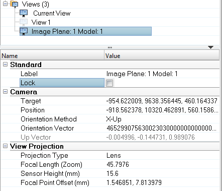
When a view is unlocked, it is also synchronized with the graphics window.
| 7. | Enter the camera properties for the view into the various fields located in the Camera section of the Entity Editor. |
Notice how the model animates with both the image placed on top of the model and the video in the background.
Step 4: Import a video as a 3D object and animate with the model.
| 1. | In the Results Browser, expand the Image Planes folder . |
| 2. | Turn off the display of the two image planes already created by selecting both Altair and Explorer, right clicking on them and selecting Hide. |
| 3. | Right click in the Results Browser and select Create > Image Plane. |
| 5. | Enter Explorer Video for the Label. |
| 6. | Click on the Open File icon next to File and select the file 06Explorer-f.avi. |
| 7. | Select the XZ Right Plane View  to align the h3d model and the avi file in the same plane. to align the h3d model and the avi file in the same plane. |
| 8. | In the Image Plane panel, verify that you are in the Alignment tab. |
This tab will be used to align the model in the video file to the model file.
| 9. | Set the Alignment Mode to 2 Point. |
| 10. | Set the Plane to XZ Right. |
| 11. | The first set of reference nodes to be selected are the h3d model’s nodes. Click on the green N1 selector to make it active, and then select the center point of the left tire in the animation window. |
If you can’t see the h3d model, simply use the Graphical Manipulator to move the video image out of the way.
| 12. | Next activate the blue N2 selector, select the center point of the right tire in the animation window, and then select Done in the panel area. |
When the two points have been selected, an arrow will be displayed going from N1 to N2.

| 13. | The same two points also need to be selected as reference nodes in the video. Click the yellow IN1 selector to make it active, and then select the center point on the left wheel of the image preview in the Image Plane panel. |
| 14. | Next click the yellow IN2 selector to make it active, and then select the center point on the right wheel. |
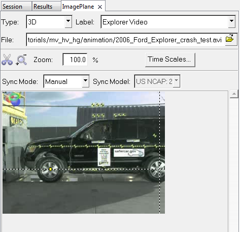
| 15. | Click Align to align the two images. |
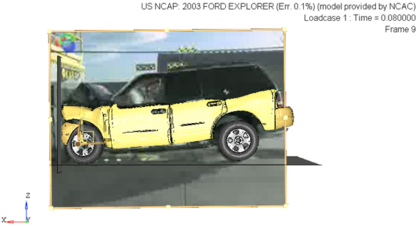
| 16. | Click Close to close the Image Plane panel. |
| 17. | Animate the model and rotate the images in the animation window. |
Notice how the video can be graphically manipulated in 3-dimensions, as well as animated with the h3d file.
See also
HyperView Tutorials for a complete list of HyperView tutorials


![]() .
. 


