Enhancements have been made in the ANSYS interface to improve the modeling and visualization of models to solve.
• | Mesh modeling enhancements |
• | Contact Manager enhancements which enable users to set ANSYS surface elements with ease and store Contact Manager settings for future use. |
When creating a mesh in previous versions of HyperMesh, you had to first select an element type of the appropriate element configuration using the Element Type panel, then you had to attach an ET Type (sensor) card to the component. This repetitive process verified that the ET Type matched that of the element type selected in the Element Type panel. In HyperMesh 14.0, you will only be required to attach the correct ET Type (sensor) to the component. The generated mesh will have the same element type as the component as long as the mesh configuration matches the element type. You will no longer be required to duplicate this information in the Element Type panel, therefore making the Element Type panel obsolete. This panel can still be used to review the element type created for a mesh. To change the element type, you will need to change the ET Type attached to the component. As long as the mesh configuration matches the element type, the elements will be updated. This enhancement has made the Update button obsolete, therefore it has been removed from the Element Type panel. The status bar can be used to verify that the component is defined correctly. If a component has valid elements but does not have an ET Type attached, the status bar will read, “Attach HM_COMP card image and ET Type” when the component is selected in the Model or Solver browsers. The status bar will also display an error if the element configuration and the ET Type do not match. Enhancements have been made to make updating the mesh easier after any mesh updating operations have been performed, such as translating, copying, organizing, and so on. By making sure that the element type is the same as the ET Type attached to the component the mesh can be easily updated. However, if a component does not have an ET Type attached or if the ET Type attached to the component is different from the configuration of the mesh being created, the mesh can still be created but the element type will be assigned the type set in the Element Type panel. New Element Type panel: Use this for review only Use Entity Editor > Component > Type to set the Element type |
Two new features have been added to the ANSYS Contact Manager.
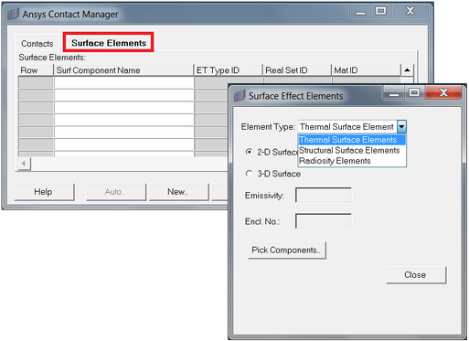
The ANSYS Contact Manager has a new tab, Surface Elements, which enables users to review existing surface element components and create new surface element components of types: thermal surface elements, structural surface elements, and radiosity elements. 2D surface elements can be created on the edges of plane elements, and 3D surface elements can be created on the faces of solid elements. Extra nodes can also be attached if the surface element type selected supports the Attach Extra Node option. This tool works similarly to the existing Contact Pairs tool in the Contact Manager. Users must select components and then select elements from the selected components to create surface elements on the faces or edges of the elements. Element key options, properties, and material properties can also be added in their respective tables that appear once the base elements have been selected. In the ANSYS Contact Manager, an option has been added to enable users to save the Contact Element Key options, Real Sets (properties), and material settings they have defined for contact pairs. This enhancement will save time when creating new contact pairs with the same Key options, Real Sets (properties), and material settings. Once the underlying elements of contact and target pairs have been selected, the Contact Manager prompts users to select applicable Key options, Real Sets (properties), and material settings. When finished, click Save Keyopts (Target Component Details dialog), Save Real Consts (Contact Property dialog), and Save Material (Contact Material dialog) to save the setting they have defined for future use. The next time a user creates a new contact pair, the settings they defined earlier are automatically applied. To restore the default settings, click Reset Defaults. All of the settings are saved in a configuration file located at: <installation\hm\scripts\ansys\ContactManager\contactpair\SavingKeyoptionsAnsys.csv. Users can edit this file directly if they choose.
|
The Midsurface extraction and meshing tool, located at Mesh > Create > Midsurf Mesh, is now fully supported for ANSYS interface with thickness assignment options. The thickness assignment options REAL SET and SECTYPE are only available for in the ANSYS user profile. Components, and properties on components are the available options as ANSYS interface only allows the indirect assignment of thickness. The REAL SET option is available for legacy ANSYS elements such as SHELL63, where a thickness is assigned to elements. For by REAL SET property and REAL SET, thickness from geometry is mapped to elements by creating a property card and assigning it a thickness. The property card will be assigned to the component of the element. The SECTYPE option can be used for the generation of new ANSYS shell elements such as SHELL181. Thickness from geometry is mapped to the Section card SECDATA with the type SHELL. The thickness value is mapped to the TK: thickness value in the SECDATA card, and creates only one layer. The section card is then assigned to the component of the element. All of the other options perform the same as in the general HyperMesh profile.
|
If CBEAM is associated with PBEAM/PBEAML, then the properties within those cards are converted to ANSYS SECTION with the type BEAM. OptiStruct/Nastran beam cross sections of types: BAR, CHAN, HAT, I, T, ROD, and TUBE are converted to ANSYS equivalent beam sections. CBEAMs are converted to ANSYS BEAM188 elements. OptiStruct/Nastran Z and BOX sections are converted to ANSYS ASEC beam sections. CHAN, Z, and BOX sections are converted only if PBEAML has a HyperBeam section attached. PBEAM is converted to ANSYS ASEC Section if HyperBeam sections are not attached to the property card. OptiStruct NSM is converted to ANSYS ADDMAS. Limitation: In this current version of the conversion tool, section offsets are not considered.
|
In earlier releases, PSHELL and PSHEAR properties are converted to ANSYS SHELL63 (if elements are first order) and SHELL93 (if elements are second order). These elements are considered legacy elements, and are not used by most users. Therefore in version 14.0,PSHELL and PSHEAR properties are converted to ANSYS SECTIONS with section type SHELL. Thickness is now mapped to the TK value in the SECDATA cards of the SHELL SECTION. CTRIA3 and CQUAD4 elements are now converted to SHELL181 instead of SHELL63 and CTRIA6 and CQUAD8 elements are now converted to SHELL281 instead of SHELL93.
|
In previous releases, the ANSYS Entity Editor contained customizations for the Et Type and Real Sets entities. In 14.0, the Entity Editor contains further customizations for the Material and SECTION entities. Tooltip help has been added for the material card MPDATA and BEAM SECTIONS. Each attribute in the material and MPDATA card has a tooltip help to indicate the type of material property and the type of input data. Tooltip help has been added to all types of sections supported under beam section collector. Tooltip help has also been added to other cards related to sections such as SECOFFSET, SECCONTROLS, SECLOCK.
|
The ANSYS model checker will now recognize contact element pairs that exist in the model. In previous versions, contact element pairs were reported under the duplicate elements error, which is incorrect.
|
The Master Degrees of Freedom used in reduced or Super element generation analysis are now read in HyperMesh as unsupported data, and will be written to the model file while exporting models from HyperMesh. Master Degrees of Freedom cannot be created in HyperMesh, currently they can only be imported and exported to prevent the loss of data.
|
HyperView now supports the user defined state variable result type SVAR. These are special result types that are defined by the user using material subroutines. These results are now available in HyperView. If a result file already has these results, the users must select the read options Rad State variable Results – Yes before reading the result file. Once the result file is read in HyperView, users must select the Result type SVAR from the result type list and pick the variable number from the drop down menu below Result type. If elemental values are intersected, select the corner results option and set the Average option to none, or set it to advance if nodal average values are required. These results type are supported as scalar results in HyperView.
|
|