HyperWorks Release Notes

CFD 14.0 Release Notes

CFD 14.0 Release Notes

Previous topic Next topic Expand/collapse all hidden text  

CFD 14.0 Release Notes

Previous topic Next topic JavaScript is required for expanding text JavaScript is required for the print function  

General


hmtoggle_arrow1Fill Hole/Gap Patch Utility

This tool is located in the mesh menu for all user profiles. It is useful utility to fill the holes and feature loops. It works for 1st order tria or quad elements. The selection makes it easier to fill the holes for selected components. It is an automated utility to fill the holes within selected components or elements. You can manually fill the holes using node/free edges selection.

cfd_14_01

hmtoggle_arrow1Merge – Disconnect components based on connectivity

The Merge and Disconnect tools are located in the Utility tab.

Merge: Merges the selected components to one component. This is useful for combining/organizing components for meshing or analysis.
Disconnect: Disconnect a component based on connectivity of mesh. This is very useful when you are working with .stl models.


hmtoggle_arrow1Mesh Control Browser:

The Mesh Control browser is located in the Mesh menu for all user profiles.

Mesh controls provide the capability to automate and streamline the meshing process for surface meshers, adaptive wrapper and volume mesher in one browser. Using mesh controls enable you to define mesh settings for all of the entities that need to be meshed in one meshing job.

Local Settings: Define local settings for surface mesher, adaptive wrapper and volume mesher.
Export/Import: Mesh settings defined in mesh controls are stored in the database. Mesh controls can also be saved to an external .xml template file for reuse in other models.


Surface Meshing Enhancements


hmtoggle_arrow1Surface Deviation Based Element Remesher

New multithreaded mesher, similar to surface deviation to remesh the elements is now available. It can be accessed via mesh controls. It captures curvature and provides smooth transition from smaller sized elements to larger sized elements. The new mesher internally identifies the elements features based on defined feature angle and captures and refines them. It provides the capability to refine the mesh based on proximity and angles specification. You can define any additional features to be captured and refined.

cfd_14_02


hmtoggle_arrow12D Mesh Refinement Controls

New options to refine 2d mesh based on the proximity, angle and shapes are added and can be accessed through mesh controls along with surface deviation meshers.

Proximity based refinement:

Provides the capability to refine surface or elements mesh based on proximity. It automatically identifies close proximity areas and refines elements based on user specification. You can define refinement based on refinement size, element size/gap ratio or through refinement curve.

cfd_14_03


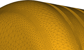
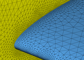
Angle based refinement:

Provides the capability to refine surface or elements mesh based on angle between surfaces or element faces. It automatically identifies refinement candidates and refines elements based on user specification. You have control over angle limits and refinement size.

cfd_14_04

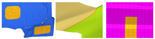
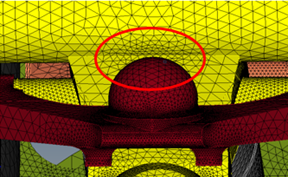
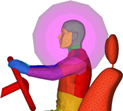
Shape based refinement

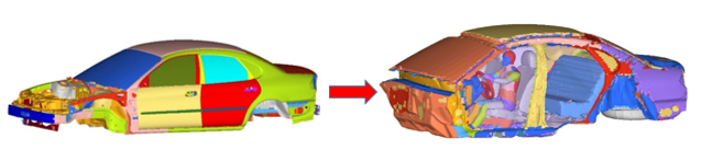
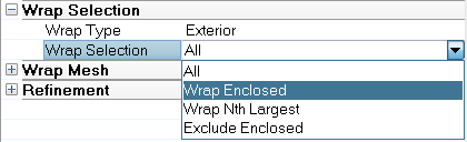
New capability to refine 2D mesh based on shapes with refinement zones. Refinement zones can be accessed within the Mesh Control browser.  You  can define box, sphere, cone, frustum, cylinder for refinement. Graphical objects provide better idea of shape definition and location. Refinement zones are used to refine mesh with a defined size. Refinement zones are also supported for surface meshing (surface deviation only), adaptive wrapper, and volume meshing.

cfd_14_05


Wrapper Enhancements


hmtoggle_arrow1Cavity Wrapper

New functionality has been added to the existing wrapper to wrap the cavity as well. With the same wrap settings, you can choose to perform exterior wrapping or cavity wrapping.

cfd_14_06

hmtoggle_arrow1Local Wrap Settings

New capability to define localized wrap settings via the Mesh Control browser. Local controls will take the precedent over global settings.


hmtoggle_arrow1Wrap Selection

New functionality to define which volumes to be wrapped is introduced. This functionality can be accessed in the Model Adaptive Wrapping Mesh Control. You have the option to wrap all the volumes, nth largest volumes, volume enclosed by seed node or exclude volume enclosed by a seed node.

cfd_14_07


hmtoggle_arrow1Improved Performance

Performance of wrapping is improved in this release. Feature capturing algorithm is much faster compared to 13.0.110. Few function is also multithreaded.


hmtoggle_arrow1Improved Leak Detection

New functionality is added to define source and target seed node for wrapping. Now you can define the enclosed node and target areas where leak checking is required. Multiple target points can be defined. It is a very useful visual utility which help to seal desired cavity. If the leak is identified, patching the gaps can be done by Fill-hole Patch tool or by increasing gap patch tolerance.

cfd_14_08


Volume Meshing Enhancements


hmtoggle_arrow1Performance Enhancements

Performance of boundary layer meshing is significantly improved in this release. 55 mi BL Penta BL elements can be generated in one hour on a full scale external aero problem compared to 5 hours in 13-110. Boundary layer meshing is completely multithreaded.


hmtoggle_arrow1Local BL Settings

New capability to define localized boundary layer settings. User can define local BL settings for desired element set or components in mesh control browser. Local controls will take the precedent over global settings.


hmtoggle_arrow1BL Aspect Ratio Based Growth Rate

New capability to define growth rate based on desired aspect ratio. This option enables the growth rate definition for boundary layers to be based on the defined aspect ratio of the final layer. After the first few initial boundary layers, if this type of growth rate method is selected, the rest of the BL will grow to achieve the user-defined Final layer height/base ratio.


hmtoggle_arrow1BL Acceleration Based Growth Rate

New capability to define BL acceleration for boundary layers. You have the option to start the accelerating BL growth after few BL layers. This option will provide the capability to achieve faster BL- tetra transition.


hmtoggle_arrow11st Layer Height as Factor of Base 2D Elements

This feature enables you to define 1st layer height as a factor of input 2d element size. This option is useful when the size of 2D elements varies significantly and a constant first layer height is not needed. With this factor, a smooth BL to tetramesh transition for large variation in 2d element size.


hmtoggle_arrow1Volume Selector

New functionality to define which volumes to mesh and option to define solid and fluid volumes before meshing has been introduced. This functionality can be accessed in the Mesh Control browser. You have the option to mesh all the volumes, largest volumes or volume touching reference elements. While selecting volume touching reference element, you can distinguish fluid and solid volume as well.

cfd_14_09


hmtoggle_arrow1Boundary Layer Contour for Visualization

This features provides new functionality to output boundary layer contours after volume meshing. This new capability provide better options for reviewing boundary layer mesh rather than masking elements or creating cross sections. You can define the option via the Volume Selector in the Mesh Controls browser. After meshing, you can load the .res file to visualize the contours of first layer BL height, number of layers generated and total boundary layer height on entire model.

cfd_14_10

hmtoggle_arrow1AcuSolve Full Import Deck Support

New capability to import AcuSolve solver settings as well while importing .inp file has been introduced. While importing AcuSolve solver decks (.inp file) the defined parameters in the solver deck will also be imported in the model and can be accessed via the Solver browser. Any unsupported parameter will be collected in “Unsupported Entries” under each folder category of the  Solver browser. You can manually edit those entries and the modified values can be exported.


hmtoggle_arrow1AcuSolve Solver Parametric Studies
Parametric Definition: You can now define discrete or continuous parameters and assign it to AcuSolve solver variables.

cfd_14_11

Parametric Studies: Once AcuSolve case is setup, parameters are defined and assigned to solver variables, you can use the HyperStudy Job Launcher to transfer all of the relevant data to HyperStudy. Afterwards, with a single click a design of experiment (DOE) study can be performed.

cfd_14_12

hmtoggle_arrow1Resolved Issues
Improved surface deviation mesher: Issues related to sliver elements has been resolved. Mesh flow has been improved. Enhanced smooth mesh across curved using better averaging of elements size
Improved rigid body mesher: Fixed the issues of rigid body mesher creates free edges. Now free edges and t-connections has been reduced significantly
Over refinement is avoided in the wrapper: Fixed the issues in wrapper to avoid over refinement where not necessary. This also results in performance improvement.