|
»Click here to display Table of Contents«
|

MotionView |

|

|

|

|
|
MotionView |
|
|

|

|
|
»Click here to display Table of Contents«
|
MotionView |
|
|
|
|
|
MotionView |
|
|
|
|
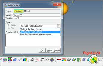
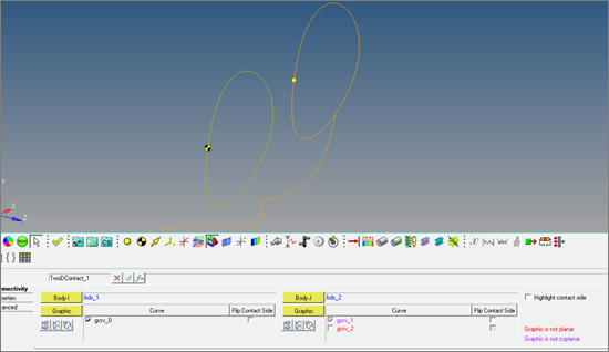
MotionSolve now supports contact between curves in a 2D plane. Along with these functions, MotionView 2017 has features for easy modeling and obtain a robust contact simulation results for Curve to Curve contacts (2D Contact). A 2D Contact can be added using the right click option on the contact toolbar. The add dialog that appears has an option in the dropdown menu.
Benefits include:
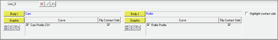
A contact panel consistent with existing 3D contact panel is now available. Select 2 bodies between which contact has to be defined. The panel will find and list all the curve graphics associated with the bodies.
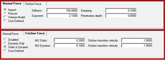
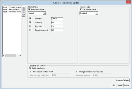
Properties tab in Contact panel for the 2D contact have the same tabs and inputs as in case of the 3D contact.
Reasonable contact and friction parameters are provided. You do not have to change these unless your contacts have special properties. Parameters are checked for validity as they are entered and the user is alerted to invalid values before the model is run. Output Requests to measure contact forces are automatically created.
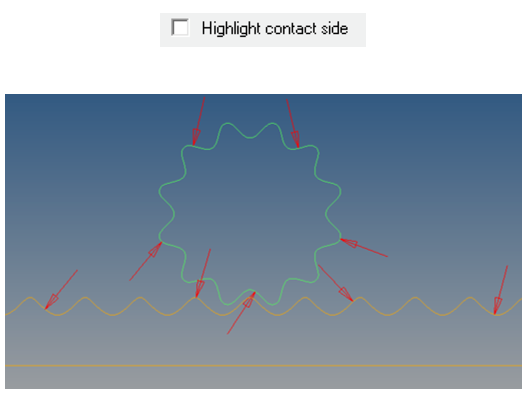
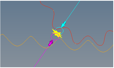
The Contact panel has an option to highlight the contact side. The graphic screen displays arrows that flow in or out of the curves. The direction of the arrow indicates onto which side of the curve the contact is expected.
The direction of contact can be flipped for any curve using the “Flip contact side” option The contact panel also checks for planarity and co-planarity of the curves. Any curve that is not planar or not co-planar with respect to the first curve of Body 1 (I Body) is highlighted in the panel.
Motionsolve requires that the curve be defined in the X-Y plane of its reference marker. MotionView provides the ability to define a curve in any arbitrary plane. If any curve is in contact, MotionView will automatically create the necessary reference.
This macro tool has been updated to take into account 2D contacts.
An “implicit graphics” contact icon is also visible. You can easily see the geometries that have 2D contact connections.
Associated graphics are highlighted when contact entity is selected.
Similar to 3D contacts, advanced options are available to detect the precise event when contact occurs. Option is also available to change the maximum step size subsequent to contact detection Using this option introduces a Sensor entity with a zero crossing attribute into the MotionSolve XML
Refer to the Rigid to Rigid Contact section in MotionView User Guide to learn more about modeling contacts.
|
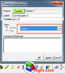
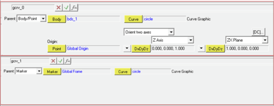
A graphic entity for any dimensional curve is now available. Apart from its usage in curve-curve contact as described above, this graphic can also be used in Advanced Joints as in Point-Curve joint and Curve-Curve Joint. To add a curve graphic, right click on the Graphics toolbar
Benefits include:
A curve graphic can be either created using an existing marker as a reference frame or the reference frame can be implicitly created using a Body/Point/Orientation method when a marker does not exist.
The graphic needs to refer to a 3D Cartesian Curve entity.
New macro “Create Curves from Points/Nodes”
Additional graphical enabled features to define curves will be available in a future version.
|
You can now register multiple wizard libraries in MotionView at a given time and shift between one library and other very easily. Benefits include:
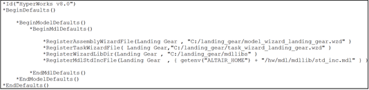
More than one wizard library can be registered now by having multiple sets of following statements in a preference file *RegisterAssemblyWizardFile *RegisterTaskWizardFile *RegisterWizardLibDir These statements register the model wizard file, task wizard file & the library directory respectively. These statements can be put in a preference file as shown below:
When the preference file is registered and loaded using File > Load > Preference File, the new library would be now available along with the existing libraries.
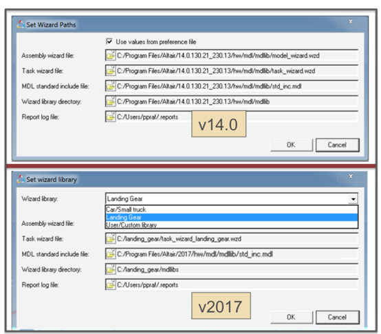
The Set Wizard path option under Model menu has been upgraded so that the user can change the current library very easily.
|
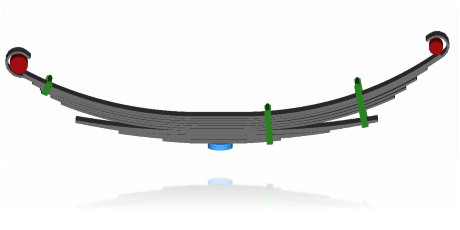
A new Leaf Spring Builder is available in MotionView in the Vehicle Tools Menu when you load the Vehicle Dynamics Tools preference file. Using the Leaf Spring Builder you describe the spring by giving the free shape of the leafs, the types of spring eyes, the shackle length, the clamped spring length at the axle, and other data then the Leaf Spring Builder outputs an MDL file containing a leaf system you can import into a suspension or full vehicle model.
Leaf Spring Builder features include:
|
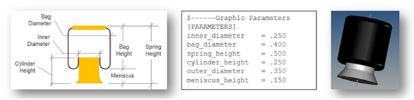
A new air spring model is available as an Auto Entity in MotionView. The air spring force is interpolated from a table of force verses spring height and static inflation pressure, which is typically published by spring manufacturers. You enter the spring trim load and trim height and MotionSolve calculates the static inflation pressure automatically. You may include a bumpstop with the air spring as well. The air spring and bumpstop force properties are read from TeimOrbit format property files. To add an air spring to your MotionView model:
The AutoAirSpring sizes graphics based on parameters in the air spring property file. In MotionView, you can update the graphics from the property file by pushing the update graphics button on the air spring panel causing MotionSolve to read the air spring property file and re-size the graphics. The air-bag graphics have a toroidal top and bottom representative of rolling lobe air spring.
|
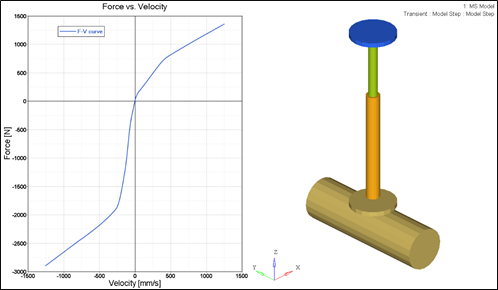
This release introduces new component test rigs, analyses, and reports for the AutoSpring, AutoAirSpring, AutoDamper, AutoBumpStop, and AutoReboundStop. Using the component test rigs allows you to easily examine the force vs displacement and force vs. velocity behavior of these auto entities. To use the component test rigs, you build a test rig model with the assembly wizard for the auto entity type you want to test, select the appropriate property file for the entity, add a component analysis using the task wizard, set the appropriate displacement and/or velocity input, run the analysis, and then view the report.
Component Test-Rig: AutoDamper Report
|
Enhanced Altair DriverFor vehicle models following a path using the feedforward steering controller in the Altair Driver overall CPU time is reduced up to 30%. The reduction was realized by optimizing evaluation of the internal bicycle model used by the feedforward steering controller to predict the vehicles path. The Altair Driver is enhanced to support steering the vehicle from steering gear (e.g. rack-pinion or recirculating ball) without the need for a steering wheel and column. The vehicle parameters input to the driver now include markers on the left and right front wheels to enable the driver to determine the overall steering ratio.
Enhanced MDLLIB Steering SystemsThe rack and pinion, parallel link, and double idler arm steering systems include new output requests for the rack travel and force, and worm shaft rotation and torque. Further the inner tie rod ball joint is lowered in the parallel link and double idler arm steering systems to reduce roll over steer.
Enhanced Bump and Rebound Stop AutoEntitiesThe bump and rebound stop AutoEntities now allow you to set the diameters of the stop graphics. Previously the diameters depended on the distance between the I and J bodies and could not be set by the user.
Enhanced MDLLIB Deformable Strut SystemThe deformable strut system now includes output requests for the spring and shock absorber displacement, velocity, and force.
|
CDTire Updated to Version 4.2.3The version of CDTire shipped with MotionSolve is updated to 4.2.3 from 4.1. CDTire version 4.2.3 includes:
The CDTire/Realtime model includes these new features:
The CDTire/3D model has these new features:
CDTire version 4.2 introduces a new Magic Formula sub model called CDTire/MF+. The MF++ model estimates the contact patch shape, location and pressure distribution for coupling with CDTire/Thermal. To select CDTire/MF++ in ADAMS via GFORCE or ADAMS/Tire (CDT_MODEL_TYPE), set the model number to 10. Note: CDTire v4.2.3 discontinues support for tire model 20 (CDT20). In addition road surface model 1000 (RSM1000) is no longer supported for use with tire model 30 (CDT30).
FTIRE MotionSolve now locates your FTIRE installation by reading the cosin_ini file in your home directory. This ensures MotionSolve uses the latest version of FTIRE installed. Previously, FTIRE binaries were shipped with MotionSolve and MotionSolve loaded FTIRE from the HyperWorks installation. Note: If you previously used FTIRE via Altair’s Partner’s Program, you must now obtain FTIRE from COSIN (www.cosin.eu) Delft-Tyre MF-TYRE/MF-SWIFTDELFT-TYRE MF-Tyre/MF-Swift 6.2.0.2 binaries are included with MotionSolve version 2017. Use of MF-Tyre with MotionView and MotionSolve is granted under the HyperWorks license. Use of MF-Swift require purchase of an additional license available from Altair.
|
MotionView memory usage is improved. In earlier versions, MotionView would accumulate memory on repeated loading of models. While an increase in memory usage is still observed for the initial 3 to 6 models opened, the memory usage stabilizes with further loading. The help link for (Advanced) Altair Driver panel in MotionView is updated to point to the correct location in the online help. In models containing AutoCDTire and AutoCTITire (FTIRE) entities, MotionView crashed when exporting the model to Adams. The definitions for AutoCDTire and AutoCTITire are updated to correct the issue.
|