|
»Click here to display Table of Contents«
|

Curve to Curve Contacts |

|

|

|

|
|
Curve to Curve Contacts |
|
|
|

|
|
»Click here to display Table of Contents«
|
Curve to Curve Contacts |
|
|
|
|
|
Curve to Curve Contacts |
|
|
|
|
The 2017 release of MotionSolve enables you to define rigid body contact between two curves that are each defined in two dimensions. Simulating rigid body contact in two dimensions between two curves is advantageous when:
| • | It is known a-priori that the contact occurs only within the plane in which the two curves are defined i.e. there are no out-of-plane contact forces that are expected. |
| • | The curves between which the contact is to be calculated are smooth and represent the curvature of the 3D geometry well |
The advantages of simulating rigid body contact using 2D curves over 3D tessellated geometry are many:
| • | More accurate results: Results are more accurate since there is lesser error due to discretization. Discretization of a 3D geometry into triangles occurs over 3 dimensions as opposed to 2 in curves |
| • | Easily improve accuracy: Accuracy of the results can be improved quicker by introducing more points in the curve within MotionView. |
| • | Improving the accuracy of results when using 3D contact requires you to re-import the graphic and re-mesh or go outside the MotionView environment into a CAD tool to re-mesh. Re-meshing a 3D geometry will certainly take more time than refining a 2D curve. |
| • | Faster simulation times: For geometries where contact occurs over a curve, using a curve-curve contact is a lot faster than using a 3D tessellated geometry since the solver has to work harder to determine contact for a 3D tessellated geometry which increases the overall simulation time |
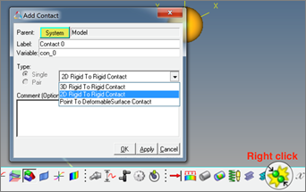
In MotionView, 2D Contact can be added using the right click option on the contact toolbar. The add dialog that appears has an option in the dropdown menu.
Benefits include:
| • | Define contact easily between geometric curves |
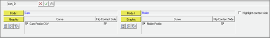
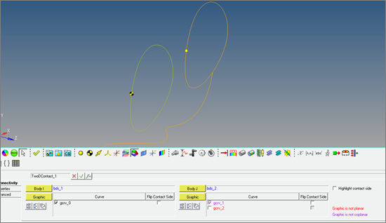
A contact panel consistent with existing 3D contact panel is now available. Select 2 bodies between which contact has to be defined. The panel will find and list all the curve graphics associated with the bodies.
| • | Contact models are defined with minimum of user input |
Properties tab in Contact panel for the 2D contact have the same tabs and inputs as in case of the 3D contact.
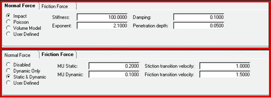
Reasonable contact and friction parameters are provided. You do not have to change these unless your contacts have special properties.
Parameters are checked for validity as they are entered and the user is alerted to invalid values before the model is run.
Output Requests to measure contact forces are automatically created.
| • | Extensive geometry checks are performed automatically to avoid potential failures in the solver |
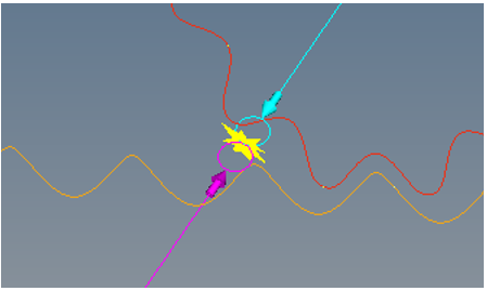
The Contact panel has an option to highlight the contact side. The graphic screen displays arrows that flow in or out of the curves. The direction of the arrow indicates onto which side of the curve the contact is expected.
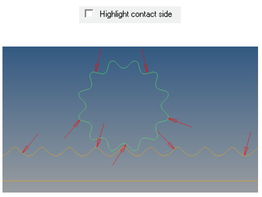
The direction of contact can be flipped for any curve using the “Flip contact side” option
The contact panel also checks for planarity and co-planarity of the curves. Any curve that is not planar or not co-planar with respect to the first curve of Body 1 (I Body) is highlighted in the panel.
Motionsolve requires that the curve be defined in the X-Y plane of its reference marker. MotionView provides the ability to define a curve in any arbitrary plane. If any curve is in contact, MotionView will automatically create the necessary reference.
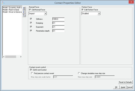
| • | Updated Contact Properties Editor Macro |
This macro tool has been updated to take into account 2D contacts.
| • | Contacts are visualized during modeling |
An “implicit graphics” contact icon is also visible. You can easily see the geometries that have 2D contact connections.
Associated graphics are highlighted when contact entity is selected.
| • | Precise contact detection is supported |
Similar to 3D contacts, advanced options are available to detect the precise event when contact occurs. Option is also available to change the maximum step size subsequent to contact detection
Using this option introduces a Sensor entity with a zero crossing attribute into the MotionSolve XML
For more details on how curve-curve contact can be defined and solved, refer to Rigid to Rigid Contact section in MotionView User Guide and Modeling Contacts in MotionSolve User Guide.