MotionSolve 14.0 introduces the “NLFE Body” which allows you to model non-linearly flexible components in your multi-body system. This is an experimental feature in the current version. The NLFE Body is based on the Absolute Nodal Coordinate Formulation (ANCF). Nonlinearity can occur for two main reasons: (A) Geometric nonlinearity and (B) Material non-linearity. The NLFE body supports both.
A non-linear modeling component is typically required in the following scenarios:
| • | A large deformation is expected in the flexible component, or an unusually large deformation is observed in the flexible component |
| • | Stresses in your flexible components approach yield point of the material |
| • | The flexible component is composed of non-linear hyper elastic materials like rubber or polyurethane. The material exhibits a nonlinear stress vs. strain behavior or is hyper-elastic |
| • | A linearly flexible modelling component does not provide the fidelity that is desired |
Please note that the deformation is still assumed to be in the elastic region. Plastic deformations are not supported in this release.
Pre-processing
MotionView has new capabilities for modeling NLFE systems. A generic NLFE Body can be created using either the CABLE or BEAM element.
The CABLE element does not resist shear or torsion forces. This implies that the cross section of this element does not change as the entity deforms.
This element can be used to model cables, wires, ropes, etc. Only the Linear Elastic material model is supported.
|
The BEAM element resists all forms of deformation, which implies that the cross section can also deform with load. This can be visualized in HyperView while using this element.
Multiple cross sections are supported for the BEAM element:
| • | Circular (solid and hollow) |
| • | Rectangular or Box (solid and hollow) |
| • | H, I, L, T and Z sections |
This element can be used to model beams, springs, belts, rubber components etc. You may choose from either a Linear-Elastic or a Hyper-Elastic material.
Three Hyper Elastic materials are supported – Neo-Hookean Compressible, Mooney-Rivlin and Yeoh models. MotionView provides a set of recommended values for the model parameters. You may however, create new materials and enter your own parameters.
|
MotionView provides 3D visualization of the NLFE body based on the profile and cross section properties.
|
An NLFE body can now have a pre-loaded position in addition to the model position. The user can import these in a CSV format. Upon import, the model position will be shown in wireframe mode and the loaded position in solid.
|
With a combination Save command in MotionSolve and a Python script, it is now possible to save the configuration of the NLFE at the end of simulation into a CSV file. This csv file can be read into MV as preloaded configuration. An option is also available to visualize the unloaded and pre-loaded profile together.
|
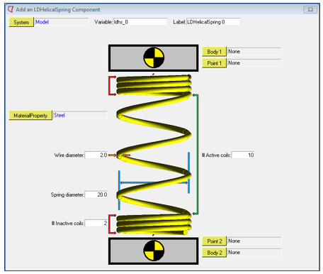
In addition to the generic Cable and Beam modeling elements, MotionView also supports a small set of NLFE subsystems that are specific to the Auto industry. These subsystems may be accessed from the vertical toolbar to the left of the graphics window. The following subsystems are supported.
Stabilizer bar
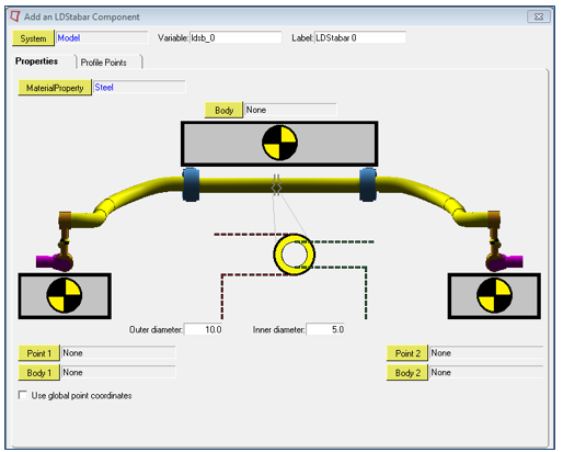
Coil spring
Refer to NLFE Subsystems to learn more about using these subsystems in your model.
These subsystems are provided as examples to you to demonstrate how the built-in capabilities of MotionView may be used to create parametric subsystems that can contain NLFE elements. You can build your own subsystems in a similar manner. Source code for the built-in NLFE subsystems will be provided in the installation.
MotionSolve supports a much larger set of NLFE modeling elements. You can use these in a MotionView model by using a Templex template. Native MotionView support is not available at this time.
|
Solution
NLFE subsystems are included in MotionSolve as a flexible body that is specified through an ANCF XML file. The MotionSolve XML file fragment below illustrates this.
<Body_Flexible
id = "30102"
label = "NLFE Body 0"
full_label = "Model-NLFE Body 0"
ref_marker_id = "30101010"
ancf_file = "simo-spinning-beam4_30102.xml"
rayleigh_damping = "0.5"
num_i_marker = "3">
30102021 30102101 30102102
</Body_Flexible>
The NLFE subsystem can consist of any combination of atomic MotionSolve NLFE elements. For the example shown above, the NLFE subsystem is specified in the file simo-spinning-beam4_30102.xml. The contents of this file are shown below.
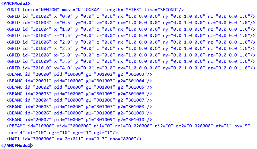
MotionSolve supports a comprehensive set of NLFE modeling elements. The table below summarizes the current implemented atomic NLFE entities in MotionSolve. Note, that MotionView supports only a small subset of these. You can use these in a MotionView model by using a Templex template.
Element Type
|
Supported Element Set
|
Line Elements
|
BEAM9
|
(Gradient Deficient ANCF Beam Element)
|
|
BEAMC
|
(Beam Element with Circular Cross Section)
|
|
BEAM12
|
(Fully Parameterized ANCF Beam)
|
|
CABLE
|
(Cable Element)
|
Surface Elements
|
QUAD12
|
(Rectangular Thick Plate Element)
|
|
QUAD9
|
(Rectangular Thin Plate Element)
|
|
TRIA12
|
(Triangular Thick Plate Element)
|
|
TRIA9
|
(Triangular Thin Plate Element)
|
Solid Elements
|
HEXA12
|
(C1 Brick Solid Element)
|
|
HEXA3
|
(C0 Brick Solid Element)
|
|
PENTA12
|
(C1 Penta Solid Element)
|
|
PENTA3
|
(C0 Penta Solid Element)
|
|
TETRA12
|
(C1 Tetra Solid Element)
|
|
TETRA3
|
(C0 Tetra Solid Element)
|
Scalar and Bushing Elements
|
ABUSH
|
(Bushing Element)
|
|
LINE2
|
(Two nodes line spring element)
|
|
LINE3
|
(Three nodes line spring element)
|
|
LINE4
|
(Four nodes line spring element)
|
Mass Elements
|
CONGM
|
(Concentrated mass element connection)
|
|
CONPM
|
(Concentrated point mass)
|
Connector Elements
|
CONN0
|
(Connector element)
|
|
CONN1
|
(Connector element)
|
|
CONN2
|
(Connector element)
|
|
CONN3
|
(Connector element)
|
Linear Elastic Material Models
|
MAT1
|
(Continuum Mechanics Approach )
|
|
MAT1LS
|
(Linear Strain Material Model)
|
|
MAT6
|
(Elastic Line Approach)
|
Hyper-Elastic Material Models
|
MAT2
|
(Incompressible Neo-Hookean Material Model)
|
|
MAT3
|
(Compressible Neo-Hookean Material Model)
|
|
MAT4
|
(Mooney-Rivlin material model)
|
Anisotropic Material Model
|
MAT7
|
(Thin Plate Element Anisotropic Material Model)
|
|
MAT7ORT
|
(Thin Plate Element Orthotropic Material Model)
|
|
MAT9
|
(Anisotropic Material Model)
|
|
MAT9ORT
|
(Orthotropic Material Model)
|
|
MAT9TRA
|
(Transverse Isotropic Material Model)
|
Geometric Properties
|
PABUSH
|
(Bushing element properties)
|
|
PBEAM9
|
(Arbitrary Cross Section Beam element properties)
|
|
PBEAMA
|
(Arbitrary Cross Section Beam element properties)
|
|
PBEAMC
|
(Circular beam element properties)
|
|
PBEAML
|
(Property card of the ANCF beam elements)
|
|
PCABLE
|
(Cable element properties)
|
|
PLINE
|
(Line spring property)
|
|
PSHELL
|
(Plate elements properties)
|
|
PSOLID
|
(Solid elements properties)
|
Other Inputs
|
GRID
UNITS
|
For more information about these elements, refer to the NLFE Reference Manual.
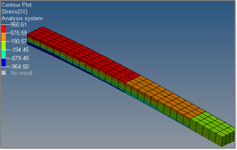
Post-processing
The result H3D contains the NLFE elements in 3D form which can be visualized in HyperView.
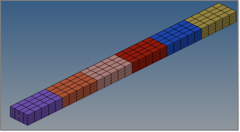
|
Displacement, stress and strain contours can be visualized on the NLFE body. Other operations such as section cuts can also be applied.
|
CMS Flexible Body vs. NLFE Body: Pre-Processing Comparison
The NLFE Body and a CMS Flexible Body provide somewhat similar capabilities. There are, however, key differences in how the entities are defined, used and in the limitations they have. Key differences between the two are compared in the tables below.
Task
|
CMS flexible body
|
NLFE body
|
Creating flexible bodies
|
User meshing is required to represent the component.
|
No user meshing required for creating NLFE sub-systems in MotionView.
|
An additional CMS analysis is required to generate a modal representation of the flexible component.
|
No analysis required to create an NLFE body. The NLFE Body can be created and modified directly in MotionView.
|
Line, shell and solid elements are supported.
|
This release introduces support for line elements only.
|
Connect to joints, forces etc. by defining interface nodes in CMS analysis.
|
All nodes can be used as interface nodes – no special handling is required.
|
Modeling flexibility in components
|
Only accurate in a linear deformation range, i.e. for small deformations;
Must capture enough modal information to represent physical deformation accurately
|
Fully non-linear formulation allows accurate solution for small and large deformations without any reduction analysis
|
CMS Flexible Body vs. NLFE Body: Solution Comparison
The solution characteristics of an NLFE Body are compared to the CMS flexible body in the following table.
Task
|
CMS flexible body
|
NLFE body
|
Modeling flexibility in components
|
Only accurate up to a linear deformation range, i.e. for small deformations.
Must capture enough modal information to represent physical deformation accurately.
|
Fully non-linear formulation allows accurate solution for small and large deformations without any reduction analysis.
|
Modeling geometric non-linearity in flexible components
|
Cannot handle large deformations in general.
|
The BEAM and CABLE element allow you to model large deformations in your flexible components.
|
Modeling material non-linearity in flexible components
|
Does not support non-linear material models.
|
You can model your flexible components with hyper elastic as well as linear elastic materials.
|
CMS Flexible Body vs. NLFE Body: Post-Processing Comparison
|
CMS flexible body
|
NLFE body
|
Recover stresses and strains
|
Yes
|
Yes. MotionSolve writes out a 3D representation of the Beam and Cable elements to enable stress, strain and displacement visualizations in HyperView.
|


