HyperWorks Solvers

/ALE/GRID/STANDARD

/ALE/GRID/STANDARD

Previous topic Next topic Expand/collapse all hidden text  

/ALE/GRID/STANDARD

Previous topic Next topic JavaScript is required for expanding text JavaScript is required for the print function  

Block Format Keyword

/ALE/GRID/STANDARD - Altair Grid Velocity Standard Formulation (2D and 3D)

Description

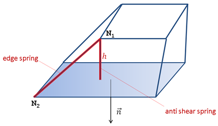
Describes the standard formulation for ALE grid velocity computation. It is an improved /ALE/GRID/SPRING formulation based on edge springs and anti-shear springs. (Comment 1)

ale_standard

Format

(1)

(2)

(3)

(4)

(5)

(6)

(7)

(8)

(9)

(10)

/ALE/GRID/STANDARD

symbol_a_14

symbol_y

symbol_n

lc


Blank Format

hmtoggle_plus1Flag Definition

Field

Contents

symbol_a_14

Scale factor for maximum stiffness (Comment 2)

= 1: critical stability stiffness limit at zero length.

= 0: default value = 0.9

< 0: elastic forces on the element edges are set to 0. It gives more weight to anti-shear springs (auto-correction).

(Real)

symbol_y

Nonlinearity factor for edge spring stiffness (Comment 3)

Default = 1e-2  (Real)

symbol_n

Damping coefficient (Comment 4)

Default = 1e-2  (Real)

lc

Characteristic length

h < lc: Edge spring stiffness is increased

h < lc / 5: Anti-shear spring is activated

(Real)

hmtoggle_plus1Comments
1.Fictitious springs are introduced on solid elements to control grid velocities.

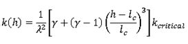
These springs are nonlinear elastic viscous. To ensure stability, their stiffness is computed from time step. The two types of springs are edge and anti-shear springs.

Edge springs

The forces for an edge spring are a function of its length variation during time.

ale_standard_edgespring

Where,

ale_standard_w are grid velocities on nodes N1 and N2, respectively.

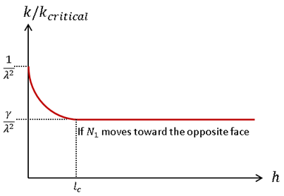
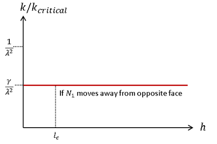
h is the N1 distance from opposite face

dt is the time step

and k(h) is the spring stiffness k(h) = kcritical

If h is inferior to the characteristic length lc and N1 is moving toward the opposite face then,

ale_standard_edgespring2

1/symbol_exp2 is the stability factor taking into account the damping factor coeffec-B, the scale factor symbol_a_14, and time step dt (Comment 4).

ale_standard_towards

otherwise, ale_standard_eq


ale_standard_away

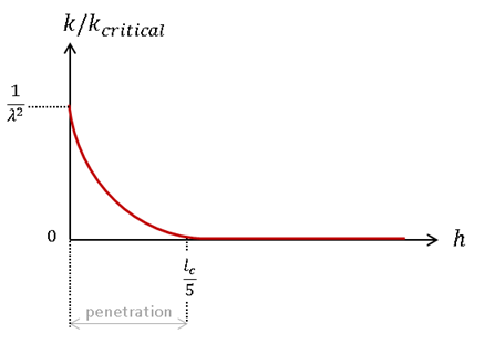
Anti-shear springs

The anti-shear forces are computed from node penetration. Gap is symbol_lc from opposite face.

ale_standard_antishear

and ale_standard_antishear2

ale_standard_critical

Viscous Damping

Viscous forces are computed from a critical damping corresponding to the upper bound for stiffness: 1/symbol_exp2

ale_standard_eq2

Grid Velocity

The grid velocity is then updated according to:

ale_standard_grid_eq

Where, m is fictitious mass on node from springs (automatically computed during Starter).

2.Increasing symbol_a_14 = 1, the maximum stiffness will be increased. The scale factor symbol_a_14 determines the maximum stiffness for a given spring at zero length. The scale factor ensures that the critical stability value is not exceeded (to avoid time step decrease).
3.This flag is acting on stiffness shape. Stiffness is linear with symbol_y = 0. Moreover, increasing symbol_y, the lower bound stiffness for edge spring will be increased. Springs have a critical stiffness at zero length (this corresponds to a unitary factor). For a length greater than or equal to the characteristic length, the spring stiffness is the critical stiffness multiplied by symbol_y.
4.It is recommended to use small values for coeffec-B , otherwise damping may become over critical. The stability factor is:

stability_factor

5.All these parameters can be modified during an Engine restart (/ALE/GRID/STANDARD).
6.Mesh auto correction. It is possible to give more weight to anti-shear forces by either:
Setting lc parameter close to the mesh size
Setting a negative value for symbol_a_14 parameter (elastic forces on edges are set to 0 at the first cycle of current run)
7.This method assumes a homogeneous spring repartition around each node. This is not the case when connecting two meshes, where topologies are different.