|
»Click here to display Table of Contents«
|

CMBEAM |

|

|

|

|
|
CMBEAM |
|
|

|

|
|
»Click here to display Table of Contents«
|
CMBEAM |
|
|
|
|
|
CMBEAM |
|
|
|
|
Bulk Data Entry
CMBEAM – Beam Element for MBD
Description
Defines a beam element for multi-body dynamics solution sequence without reference to a property entry.
Format
(1) |
(2) |
(3) |
(4) |
(5) |
(6) |
(7) |
(8) |
(9) |
(10) |
CMBEAM |
EID |
MID |
GA |
GB |
X1, G0 |
Y1 |
Z1 |
L |
|
|
A |
I1 |
I2 |
J |
K1 |
K2 |
|
|
|
|
Field |
Contents |
EID |
Unique element identification number. (Integer > 0) |
MID |
Material identification number. Only MAT1 material definitions may be referenced by this element. (Integer > 0) |
GA, GB |
Grid point identification number of connection points. (Integer > 0; GA ≠ GB) |
X1, Y1, Z1 |
Components of vector v at end A, measured at end A, parallel to the components of the displacement coordinate system for GA, to determine (with the vector from end A to end B) the orientation of the element coordinate system for the BEAM element. (Real) |
G0 |
Grid point identification number to optionally supply X1, X2, and X3 (Integer > 0). Direction of orientation vector is GA to G0. (Integer > 0) |
L |
Undeformed length along the X-axis of the beam. (Real) |
A |
Area of the beam cross-section. No default (Real > 0.0) |
I1 |
Area moment inertia in plane 1 about the neutral axis. No default (Real > 0.0) |
I2 |
Area moment inertia in plane 2 about the neutral axis. No default (Real > 0.0) |
J |
Torsional constant. (Real > 0.0) |
K1, K2 |
Area factor for shear. Default = 0.0 (Real) |
| 1. | The X-axis of the beam is always along the line connecting G1 and G2. The Z-axis of the beam is determined based on the X-axis and the Y-axis provided by G3/X1, Y1, and Z1. |
| 2. | The moments of inertia are defined as follows: |
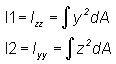
The beam coordinates must be aligned with the principal axes of the cross-section.
| 3. | The transverse shear stiffness in planes 1 and 2 are (K1)AG and (K2)AG, respectively. If a value of 0.0 is used for K1 and K2, the transverse shear flexibilities are set to 0.0 (K1 and K2 are interpreted as infinite). |
| 4. | This card is represented as a bar2 element in HyperMesh. |
See Also: