| 1. | Constraint_Jprim defines a set of holonomic constraints between two bodies in the model. These constraints allow the two connected bodies to only have relative motion in certain specific directions. Motion in all the other directions is prohibited. |
| 2. | In their most general form, constraints can involve displacements, velocities, and time. Constraint_Jprim elements are distinguished by the fact that they only involve displacements. The constraint relationships do not involve velocities or time explicitly. Therefore, they do not add or remove energy from the system. |
| 3. | An internal reaction force or moment is associated with each constraint in a Constraint_Jprim. This internal reaction ensures that the relative motion of the bodies specified in the connector satisfies the constraints. The reaction force in a Constraint_Jprim may be accessed using the JPRIM() function expression. |
The internal reaction forces and moments at each Reference_Marker of the primitive obey Newton’s third law of motion. Their magnitude and direction is such that they cancel each other out as shown in Figure 1 below.
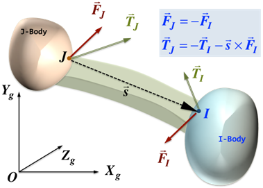
Figure 1: Internal force and torque balance in a Constraint_Jprim
| 4. | It is possible to "over-specify" the constraints in a model. In this case, the system is said to be over-constrained, and the constraints are said to be "redundant". Consider a door connected to a frame as shown in Figure 2 below. |
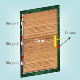
Figure 2: A simple system with redundant constraints
Both the door as well as the frame are assumed to be rigid. Three hinges connect the door to the frame, allowing the door to open and close. The hinges are modeled as revolute joints. In this idealization, the hinges are assumed to be massless and rigid. Each hinge allows rotation between the door and the frame about an axis, shown as a red arrow in Figure 3:
In this idealization, a few points should be noted:
| • | The hinge axes are required to be perfectly collinear. Otherwise, the door cannot be opened or closed. |
| • | Only one hinge is truly necessary. The remaining two are "redundant". |
If such a system is provided to MotionSolve, it will detect a redundancy in the constraints and remove the equivalent of two hinges from the model. It will solve the system so that the correct motion is predicted.
The effect of removing two hinges from the solution process is to set their reaction forces to zero. Clearly, this is unexpected behavior. In reality, all three hinges have reaction forces and torques. This is an issue with the idealization of the system. If at least one of two bodies, the door or the frame, were made flexible, then more realistic reactions would be observed at each hinge.
This is a constraint primitive that requires that the origin of a Reference_Marker on Body-2 stay superimposed on the origin of the Reference_Marker placed on Body-1. All rotations are allowed but no translations are allowed. Figure 3 shows a schematic of an ATPOINT constraint primitive.
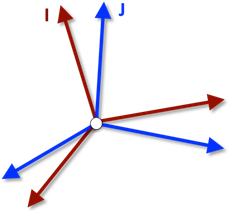
Figure 3: A schematic of an ATPOINT constraint primitive
This is a constraint primitive that requires that the origin of a Reference_Marker on Body-1 translates along the z-axis of a Reference_Marker placed on Body-2. All rotations are allowed. Figure 4 shows a schematic of an INLINE primitive.
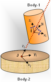
Figure 4: A schematic of an INLINE primitive
The inline primitive constrains two translational degrees of freedom. It prohibits translation along the x- and y-axes of the Reference_Marker on Body-2.
This is a constraint primitive that requires that the origin of a Reference_Marker on Body-1 (I in the figure below) to stay in the XY plane defined by the origin of the J Reference_Marker and its z-axis. Figure 5 shows a schematic of an INPLANE primitive.
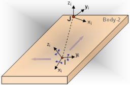
Figure 5: A schematic of an INPLANE primitive
The INPLANE primitive constrains one translational degree of freedom. It prohibits translation along the z-axis of the Reference_Marker J on Body-2. All rotations are allowed.
Figure 6 shows a schematic of an ORIENTATION primitive. It requires that the orientation of a Reference_Marker on Body-1 (I in the figure below) always be the same as the orientation of a Reference_Marker on Body-2 (J in the figure below).
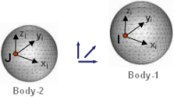
Figure 6: An ORIENTATION primitive
The ORIENTATION primitive removes three degrees of freedom; all of these are rotational. All three translations of Body-1 with respect to Body-2 are allowed.
Figure 7 shows a schematic of a PARALLEL_AXES primitive. This primitive constrains Body-1 such that the z-axis of a Reference_Marker (I in the figure below) is always parallel to the z-axis of a Reference_Marker on Body-2 (J in the figure below).
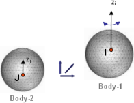
Figure 7 A PARALLEL_AXES primitive
The PARALLEL_AXIS primitive removes two rotational degrees of freedom. Rotation of Body-1 is only allowed about the z-axis of the J Reference_Marker. All three translations are allowed.
| 10. | type = "PERPENDICULAR" |
Figure 8 shows a schematic of a PERPENDICULAR_AXES primitive. This primitive constrains Body-1 such that the z-axis of a Reference_Marker (I in the figure below) is always PERPENDICULAR to the z-axis of a Reference_Marker on Body-2 (J in the figure below).
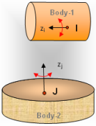
Figure 8: A PERPENDICULAR_AXES primitive
The PERPENDICULAR_AXIS primitive removes one degree of freedom. Rotation of Body-1 is only allowed about the z-axis of the I Reference_Marker and the z-axis of the J Reference_Marker. All three translations are allowed.
|


