|
»Click here to display Table of Contents«
|

CTETRA |

|

|

|

|
|
CTETRA |
|
|

|

|
|
»Click here to display Table of Contents«
|
CTETRA |
|
|
|
|
|
CTETRA |
|
|
|
|
Bulk Data Entry
CTETRA – Four-sided Solid Element with four or ten grid points
Description
Defines the connections of the CTETRA element.
Format
(1) |
(2) |
(3) |
(4) |
(5) |
(6) |
(7) |
(8) |
(9) |
(10) |
CTETRA |
EID |
PID |
G1 |
G2 |
G3 |
G4 |
G5 |
G6 |
|
|
G7 |
G8 |
G9 |
G10 |
|
|
|
|
|
|
CORDM |
CID |
|
|
|
|
|
|
|
|
Field |
Contents |
EID |
Unique element identification number. No default (Integer > 0) |
PID |
A PSOLID property entry identification number. Default = EID (Integer > 0) |
G# |
Connected grid points identification number. Default = blank (Integer > 0) |
CORDM |
Flag indicating that the following field references the material coordinate system. |
CID |
Identification number of the material coordinate system. Default = 0 (Integer ≥ -1) |
| 1. | The grid points G1, G2, G3, and G4 must describe the vertices and the remaining grid points describe mid side nodes in the order shown here: |
The edge points G5 to G10 are optional. All or none of the edge points can be specified.
It is recommended that the edge points be located within the middle third of the edge.
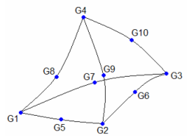
CTETRA definition
| 2. | If the user-defined node numbering on the bottom face is reversed as compared to the sequence shown above, the nodes are renumbered to produce right-handed orientation of numbering. This is accomplished by swapping node G2 with G3. For 10-noded CTETRA, appropriate changes to mid-side node numbering are also performed. In such cases, the element coordinate system will be built on the renumbered node sequence. |
| 3. | Stresses are output in the material coordinate system. The material coordinate system is defined on the referenced PSOLID entry. It may be defined as the basic coordinate system (CORDM = 0), a defined system (CORDM = Integer > 0), or the element coordinate system (CORDM = -1). |
| 4. | The element coordinate system for the CTETRA element is defined as follows: |
Three intermediate vectors R, S, and T are chosen by the following rules:
R |
Joins the midpoints of the edges from G1 to G2 and G3 to G4. |
S |
Joins the midpoints of the edges from G1 to G3 and G2 to G4. |
T |
Joins the midpoints of the edges from G1 to G4 and G2 to G3. |
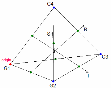
CTETRA element coordinate system
The origin of the element coordinate system is located at G1.
The element z-axis corresponds to the T vector.
The element y-axis is the cross product of the T and R vectors.
The element x-axis is the cross product of the element y-axis and the element z-axis.
| 5. | This card is represented as a tetra4 or tetra10 element in HyperMesh. |
See Also: