Cylindrical Joint (/CYL_JOINT) |

|

|

|

|
|
Cylindrical Joint (/CYL_JOINT) |

|

|

|

|
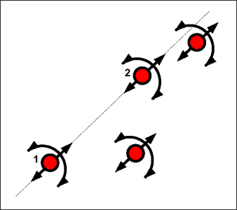
A cylindrical joint is like a rigid body, except that one specific direction is defined with the first two slave nodes. All nodes are free to move along this direction and to rotate around it. A kinetic condition is applied on all slave nodes, including the first two defining the privileged direction No master node is used.

Fig. 4.15: Cylindrical joint
If all the slave nodes are initially aligned, they will always remain aligned. As visualized in Fig. 4.15 the rotation freedom is a local rotation for each node and not a global rotation around axis 1-2. Therefore, it is recommended to use a cylindrical joint with aligned nodes.

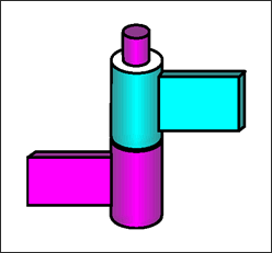
Fig. 4.16: Door hinge example
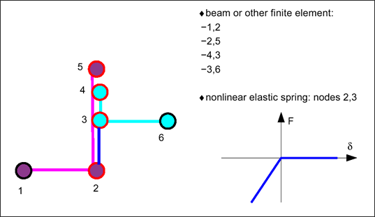
Above is an example of how a hinge could be modeled using a cylindrical joint. The cylindrical joint is made of nodes 2, 5, 3 and 4. Note that in hinge modeling nodes must be aligned to get a realistic rotation, then beams or any other finite elements are used to connect nodes 1-2, 2-5, 4-3 and nodes 3-6. Finally, it is possible to link nodes 2-3 with a nonlinear elastic spring to improve the connection.

Fig. 4.17: Hinge modelization