Definition
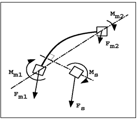
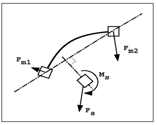
Interface type 2, also called 'tied interface' is a nodal constraint to rigidly connect a set of slave nodes to a master surface. The slave nodes forces and moments are transferred to the master nodes, and then slave nodes are positioned kinematically according to the motion of the master nodes. This interface ensures a full force and moment equilibrium.
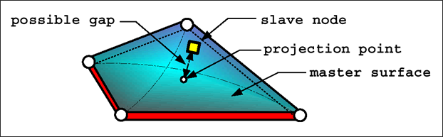
Fig. 4.10: Interface type 2 - Tied
There are four formulations are available to describe this connection.
| • | Default spotweld formulation |
| • | Optimized sportweld formulation |
| • | Formulation with failure |
Default Spotweld Formulation
SPOTflag=0
When the flag is set to 0, the spotflag formulation is a default formulation:
| • | Based on element shape functions |
| • | Generate hourglass with under-integrated elements |
| • | Give a connection stiffness function of slave node localization |
| • | Recommended with fully-integrated shells (master) |
| • | Recommended for connecting brick slave nodes to brick master segments (mesh transition without rotational freedom) |
Optimized Spotweld Formulation
SPOTflag=1
When the flag is set to 1, the spotflag formulation is an optimized formulation:
| • | Based on element mean rigid motion |
| • | Constant connection stiffness |
| • | Recommended with under-integrated shells (master) |
| • | Recommended for connecting beam, spring, and shell slave nodes to brick master segments |
Formulation with Failure
SPOTflag=20, 21 and 22
Using these options, the following two failure criteria can be defined:
Rupt= 0 (independent rupture parameters):
failure when  or
or  are reached (default)
Rupt= 1 (coupled rupture parameters):
failure when 
During the computation, a normal stress, shear stress, normal displacement and tangential displacement are computed and compared to the maximum values defined in the interface. As soon as the maximum criteria have been reached, the normal stress and shear stress will be set to 0.
Penalty Formulation
SPOTflag=25
The main goal for interface type 2 using penalty method is to tie slave node to master segment without any kinematic constraints. Using the penalty method may avoid "INCOMPATIBLE KINEMATIC CONDITIONS".


