|
»Click here to display Table of Contents«
|

/INTER/TYPE2 |

|

|

|

|
|
/INTER/TYPE2 |
|
|

|

|
|
»Click here to display Table of Contents«
|
/INTER/TYPE2 |
|
|
|
|
|
/INTER/TYPE2 |
|
|
|
|
Block Format Keyword
/INTER/TYPE2 - Interface Type 2
Description
Defines a TYPE2 tied interface that kinematically connects a set of slave nodes to a master surface. It can be used to connect coarse and fine meshes, model spotwelds, rivets, and so on.
Format
(1) |
(2) |
(3) |
(4) |
(5) |
(6) |
(7) |
(8) |
(9) |
(10) |
/INTER/TYPE2/inter_ID/unit_ID |
|||||||||
inter_title |
|||||||||
grnd_IDs |
surf_IDm |
Ignore |
Spotflag |
Level |
Isearch |
Idel2 |
|
dsearch |
|
Read this input, if Spotflag = 20, 21, or 22:
(1) |
(2) |
(3) |
(4) |
(5) |
(6) |
(7) |
(8) |
(9) |
(10) |
Rupt |
Ifiltr |
fct_IDsr |
fct_IDsn |
fct_IDst |
Isym |
Max_N_Dist |
Max_T_Dist |
||
Fscalestress |
Fscalestr_rate |
Fscaledist |
Alpha |
Area |
|||||
Read this input, if Spotflag = 25 or 26 (Optional):
(1) |
(2) |
(3) |
(4) |
(5) |
(6) |
(7) |
(8) |
(9) |
(10) |
Stfac |
Visc |
|
|
Istf |
|
|
|
||
Read this input (Optional):
(1) |
(2) |
(3) |
(4) |
(5) |
(6) |
(7) |
(8) |
(9) |
(10) |
Ithe |
Kthe |
|
|
|
|
|
|
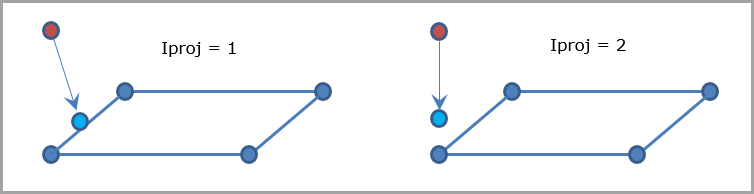
Iproj |
|
|
with, n being the number of master segments, and di is the total length of all the master side segments. A possible workaround is using Spotflag=2, which corresponds to the default formulation (Spotflag=0); except that it is not compatible with /DT/NODA/CST.
The reduced force is compared to the max value: if if Here the max value will be defined by the user with:
Once the rupture criterion (defined by Rupt) is reached, the contact will be deleted. Here:
This failure option (Spotflag = 20, 21 or 22) can not be used in implicit.
Warning: This formulation is not compatible with solid elements, since it requires rotational DOF.
The penalty stiffness is constant, calculated as the mean nodal stiffness of master and slave side. The stiffness factor, Stfac, may be used to modify it, if needed. The penalty stiffness will be multiplied by Stfac. A critical viscous damping coefficient (Visc) allows damping to be applied to the interface stiffness. Spotflag =26 is similar to Spotflag =25, but with added transmission of rotational moments from slave to master.
If Ignore = 2 or 3 and dsearch = 0, dsearch is computed, as follows for each slave node:
dsearch = max( For shells:
For solids:
If Ignore = 2:
If Ignore = 3: thickness_master segment = 0 If Ignore = 2 or =3: Thickness is retained in the following order: first from /PART definition, from /SHELL or /SH3N definition, then from /PROP definition.
Istf = 1: Kn = Stfac * Km Istf = 2: Istf = 3: Kn = Stfac * max (Km,Ks) Istf = 4: Kn = Stfac * min (Km,Ks) Istf = 5:
Thermal conduction is computed when the slave node falls into contact. The heat exchange is computed from master to slave and from slave to master:
|
Interface type 2 in User's Guide
Interface type 2 in FAQ (Kinematic Conditions)
Interface type 2 in FAQ (Contact Interfaces)
Interface type 2 in Theory Manual