|
»Click here to display Table of Contents«
|

Kinematic Conditions |

|

|

|

|
|
Kinematic Conditions |
|
|

|

|
|
»Click here to display Table of Contents«
|
Kinematic Conditions |
|
|
|
|
|
Kinematic Conditions |
|
|
|
|
WARNING ID: 147 *** WARNING: INCOMPATIBLE KINEMATIC CONDITIONS 2 KINEMATIC CONDITIONS ON NODE
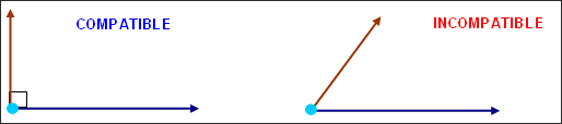
Conditions upon node velocity Two kinematic conditions which apply at the same time along non-orthogonal directions are considered incompatible. For instance, a boundary constraint on a node in X direction of the global system and an imposed velocity in the same direction are not compatible (such a behavior is not possible). On the other hand, a boundary constraint on a node in X direction of the global system and an imposed velocity in Y or Z direction of the global system are compatible. Since a rigid body controls the movement of its slave nodes, a rigid body slave node can not use another condition (specifically it cannot belong to another rigid body). If flag Ikrem of the rigid body gets its default value =0, the slave nodes of the rigid body are automatically suppressed of the rigid walls; the master node of the rigid body will realize the contact with the rigid walls if it is declared as a slave node of the rigid walls. In case some conditions are incompatible and are applied at the same time on a node, the model behavior is not guaranteed, since those conditions will not be correctly taken into account. The /PARITH/ON option is not supported in this case, so it is necessary to check the source of those WARNINGS and to adapt the model. In case of two incompatible conditions that are never applied at the same time (for instance, because their activation intervals [Tstart, Tstop] do not overlap); the WARNINGS need not be taken into account. Moreover, no error is written by RADIOSS Starter better than these WARNINGS, which would prevent from running the computation, since the analysis of the compatibility of the kinematic conditions is sometimes more complex than RADIOSS Starter can manage. In such cases, the WARNINGS provide the only clue to error termination of the run and it is your responsibility to check the model. |
**ERROR: RIGID BODY 345886 UNSTABLE
This means that:
where, vr is the rotational velocity of the rigid body and dt is the time step. The rigid body turns more than one radian per cycle. This situation is due to divergence in the computation. The model and its behavior must be checked. |
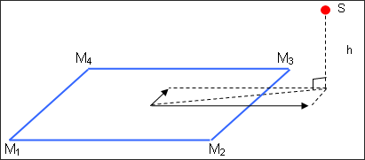
WARNING ID: 345 *** WARNING/CHECK TIED INTERFACE 93836629 1218 601311 601309 601310 601312 1.0218 -0.0095 1.339E-01
93836629 1218 601311 601309 601310 601312 1.0218 -0.0095 1.339E-01 # S Seg M1 M2 M3 M4 r s h
This message is written when the value of r or the value of s is not between -1 and 1, that is to say that the slave node projects out of the closest master segment.
This message is not due to the height of the slave node with respect to the master segment. In case the Interface Type 2 with Spotflag =0, this can cause an error in RADIOSS Engine at the first cycle, due to a negative mass or inertia of a master node of the segment. This can also cause an error in RADIOSS Engine during the run due to a negative stiffness on a master node of the segment: ** ERROR : NEGATIVE STIFFNESS NODE … In case of the Interface Type 2 with Spotflag =1, the situation corresponding to this message can cause a relatively important added mass at the first cycle on the master nodes of the segment.
WARNING ID: 86 ** WARNING: TIED INTERFACE TIED INTERFACE: 4533 5490 248 5430 5250 5490 5491 1.00734 1.14868 This message corresponds to search formulation for the closest master segment Isearch =1. The meaning and possible consequences of this message are the same as for WARNING ID: 345. |
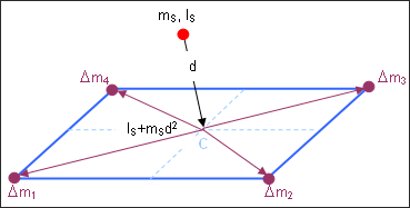
If option Spotflag =1 is used in the Interface Type 2, then there are added mass on master nodes at the first cycle of RADIOSS Engine. Indeed the slave node inertia with respect to the center of the closest master segment – let IS + mSd2 where, IS is the slave node inertia; mS is its mass and d is its distance to the center of the segment - is equilibrated by added mass on master nodes. When creating a spot weld with spring and Interface Type 2, it is important to check that the springs inertia (I =m*L2) are not too large - that is to say, that they correspond to the physics – and that the slave nodes height with respect to the master segments is as small as possible. Indeed, the geometrical concordance is necessary for Interface Type 2 to work normally, and will help getting a lower added mass due to term mSd2.
|
|
** WARNING IN RIGID BODY DEFINITION NODE ID= 167467 IS MASTER OF RIGID BODY NUMBER 25 AND SLAVE OF ANOTHER ONE
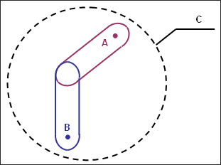
The standard formulation for rigid bodies is not working if a master node of a rigid body appears as a slave node of another rigid body; except for rigid bodies using Lagrange multipliers (/RBODY/LAGMUL). In the figure below, three rigid bodies A, B and C are defined. The master nodes of A and B have an added mass so that the centers of mass of the rigid bodies A and B are not centered. For representing the rigid body motion of the whole system A+B, a rigid body C has been defined using all slave nodes of A and B and also including the master nodes of A and B in order to take into account the added mass on these master nodes. Then the message is written by RADIOSS Starter and the rigid bodies A, B and C absolutely can not be used at the same time (the results would be arbitrary). On the other hand, we can stand from the same Runname_0000.rad to study the whole system C=A+B rigid body motion by deactivating rigid bodies A and B (/RBODY/OFF) and activating rigid body C (/RBODY/ON), whether the independent behaviors of A and B by activating rigid bodies A and B (/RBODY/ON) and deactivating rigid body C (/RBODY/OFF). The activation/deactivation of rigid bodies can be realized by using options /RBODY/ON and /RBODY/OFF in RADIOSS Engine or by defining SENSORS.
|