Summary
The aim of this example is to introduce solid element modeling for spotweld connection.
Title
Solid Spotweld
|
|
Number
48.1
|
Brief Description
Solid spotweld defined with /MAT/LAW59 and /FAIL/CONNECT connect two metal sheets with tied contact.
|
Keywords
| • | Shell element (for sheet metal) |
| • | Tied contact interface /INTER/TYPE2 (between solid spotweld and sheet metal) |
| • | Material law /MAT/LAW59 and failure model /FAIL/CONNECT for solid spotweld |
| • | Solid element property for connect material /PROP/TYPE43 for solid spotweld |
| • | Johnson-Cook elasto-plastic material law /MAT/LAW2 for sheet metal |
|
RADIOSS Options
|
Input File
Frame Modified: <install_directory>/demos/hwsolvers/radioss/48_solid_spotweld/*
|
Technical / Theoretical Level
Advanced
|
Overview
Physical Problem Description
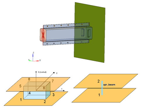
A steel crash box with solid spotweld, fixed at one end, is impacted at the other end by a rigid wall. The dimensions of the crash box are 333.6 mm x 122.7 mm x 68.28 mm, and its thickness is 1.8 mm.
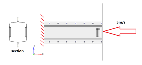
Fig 1: Problem description and beam cross section
Units: mm, s, Mg , N , MPa
Using the Johnson-Cook plasticity model (/MAT/LAW2), the sheet metal material has the following characteristics:
| • | Initial density = 7.8e-9 [Mg/mm3] |
| • | Young modulus = 210000 [MPa] |
| • | Yield stress = 250 [MPa] |
| • | Hardening parameter = 350 [MPa] |
| • | Hardening exponent = 0.3 |
In this connection material (/MAT/LAW59) use stress - plastic strain curve to describe the material characters of spot-weld. With failure model (/FAIL/CONNECT) it is possible to use two different failure criteria to describe the failure of solid spot. In this example, use the following characteristics:
| • | Initial density = 7.8e-9 [Mg/mm3] |
| • | Young modulus = 210000 [MPa] |
| • | Failure relative displacement in normal direction = 1.0 |
| • | Failure relative displacement (elongation) in tangential plane = 1.8 |
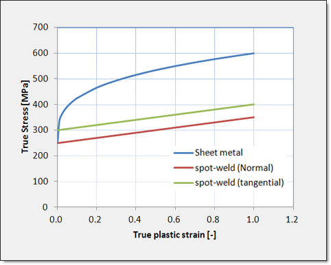
Fig 2: Material curve of sheet metal and solid spotweld.
In this simple example a linear behavior of spotweld has just been assumed. For more accurate results, you can also put nonlinear behavior of spotweld through real physic test and CAE validation.
Analysis, Assumptions and Modeling Description
Modeling Methodology of Solid Spotweld
Solid spotweld will be modeled as follows:
| • | /MAT/LAW59 to define the material |
| • | /FAIL/CONNECT to define the rupture criteria |
| • | /INTER/TYPE2 to define the connection between spotweld and sheet metal |
Comments
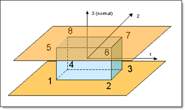
| 1. | In this spotweld modeling surface 1 (Node 1, 2, 3, and 4) and surface 2 (Node 5, 6, 7, and 8) are defined. The normal direction has been defined from surface 1 to surface 2. |
| 2. | Surface 1 and 2 for each solid spotweld should always connect with a shell element. If one surface of one solid spotweld is not connected with a shell element, then the stiffness will not be computed correctly and an error may occur. |
RADIOSS Options Used
Rigid body and Boundary conditions:
| • | One end of the crash box is modeled using a rigid body and this rigid body is completely fixed using translations and rotations. |
Rigid wall:
| • | The impactor is modeled using a moving rigid wall having a fixed velocity (5 m/s) in a X direction and is fixed for other translations and rotations. |
Interface:
| • | The structure interaction is modeled using a type 7 interface on the full structure with self-impact, where the master surface is defined using the complete model and the slave nodes group is defined using the master surface. |
Simulation Results and Conclusions
With /ANIM/BRICK/TENS/STRAIN and /ANIM/BRICK/TENS/STRESS you get the strain and stress results of the solid spotweld (see below).
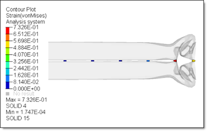
Fig. 3: Strain of solid spotweld
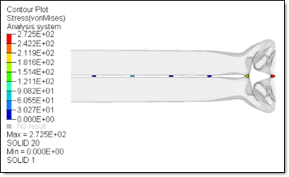
Fig. 4: Stress of solid spotweld
Here in the model you define max. relative displacement in normal direction EPS_N_MAX=1.0 in option /FAIL/CONNECT. Therefore, two solid spotwelds (circled in red) failed after reaching this criterion.
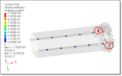
Fig. 5: Strain of solid spotweld (display erode element in HyperView)
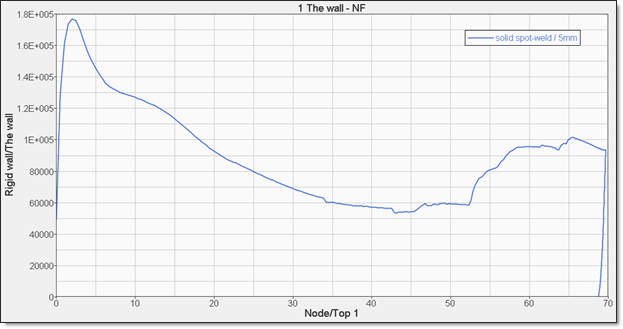
Fig. 6: Force vs displacement of crashbox
Performance
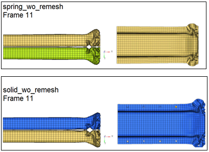
Compared with spring beam spotweld molding, the following performance could be observed:
If you use this solid spotweld modeling, it shows less sheet metal mesh size dependence compared with spring beam element.
| • | With coarse sheet metal mesh size, you got similar deformation and similar Force vs Displacement curve for solid spotweld modeling and spring beam spotweld modeling. |
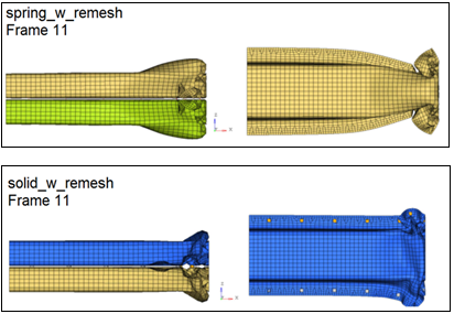
| • | Once you remesh the sheet metal shell element with fine mesh size (for example with 2.5mm mesh size here), then you still get similar deformation and Force vs Displacement curve in solid spotweld modeling but not in spring beam spotweld modeling. This means less sheet metal mesh size dependence for this new solid spotweld modeling. |
| • | The solid spotweld element is time step is free. The element stability is assured by its nodal connection. The node of the solid element must be connected (tied interface, common nodes, and rigid connection). |
| • | The solid spotweld element height (length in local Z direction) can be null and the spotweld results are independent from its height. |
| • | Strain rate of solid spotweld can be taken into account. |


