Summary
RADIOSS includes the material model CONC to model concrete failure modeling under compression and tension.
Three kinds of tests are performed in this example:
| • | Uniaxial tests (uniaxial compression and uniaxial tension) where experimental results have been used to calibrate the model reference |
| • | Multi-axial tests to evaluate the simulation/experiment correlation |
| • | Cyclic tests to illustrate the right behavior of the model used |
In order to simulate this experience, a model is created with the following details:
| • | A one element cube with eight node brick elements |
The simulation results are then compared to the experiment data.
Title
Concrete Validation
|
|
Number
47.1
|
Brief Description
Three kinds of tests are performed in order to evaluate the simulation/experiment correlation and to illustrate the good behavior of the model used.
|
Keywords
|
RADIOSS Options
| • | Boundary condition (/BCS) |
|
Input File
Concrete Failure: <install_directory>/demos/hwsolvers/radioss/47_concrete_test/*
|
Technical / Theoretical Level
Advanced
|
Overview
Physical Problem Description
The purpose of this example is to compare the simulation results to experimental data.
A concrete cube is subjected to various tests:
Kupfer Tests [2]
Units: mm, ms, mg, MPa
The Concrete material law (/MAT/LAW24) has the following characteristics:
| • | Initial density = 0.0022 mg/mm3 |
| • | Concrete elasticity Young’s modulus Ec = 31700 MPa |
| • | Poisson’s ratio  = 0.22 = 0.22 |
| • | Concrete uniaxial compression strength fc = 32.22 MPa |
| • | Concrete biaxial strength fb/fc = 1.15 |
| • | Concrete confined strength f2/fc = 4.2 |
| • | Concrete confining stress so/fc = 0.8 |
| • | Concrete plasticity initial value of hardening parameter ky = 0.35 |
| • | Concrete plasticity dilatancy factor at yield αy = -0.6 |
| • | Concrete plasticity dilatancy factor at failure αf = -0.2 |
#---1----|----2----|----3----|----4----|----5----|----6----|----7----|----8----|----9----|---10----|
/MAT/CONC/1
Concrete
# RHO_I
.0022 0
# E_c NU
31700 .22
# fc ft_on_fc fb_on_fc f2_on_fc s0_on_fc
32.22 0 1.15 4.2 .8
# H_t D_sup EPS_max
0 0 0
# k_y r_t r_c H_bp
.35 0 0 0
# ALPHA_y ALPHA_f V_max
-.6 .2 0
# f_k f_0 H_v0
0 0 0
# E sigma_y E_t
0 0 0
# ALPHA1 ALPHA2 ALPHA3
0 0 0
#---1----|----2----|----3----|----4----|----5----|----6----|----7----|----8----|----9----|---10----|
|
Schickert and Winkler Tests
Units: mm, ms, mg, MPa
The Concrete material law (/MAT/LAW24) has the following characteristics:
| • | Initial density = 0.0022 mg/mm3 |
| • | Concrete elasticity Young’s modulus Ec = 23000 MPa |
| • | Poisson’s ratio = 0.19 |
| • | Concrete uniaxial compression strength fc = 30.6 MPa |
| • | Concrete data tensile tangent modulus Ht = -31700 |
| • | Concrete plasticity initial value of hardening parameter ky = 0.35 |
| • | Concrete plasticity base plastic modulus Hbp = 29170 |
| • | Concrete plasticity dilatancy factor at yield αy = -0.6 |
| • | Concrete plasticity dilatancy factor at failure αf = -0.2 |
#---1----|----2----|----3----|----4----|----5----|----6----|----7----|----8----|----9----|---10----|
/MAT/CONC/1
Concrete
# RHO_I
.0022 0
# E_c NU
23000 .19
# fc ft_on_fc fb_on_fc f2_on_fc s0_on_fc
30.6 0 0 0 0
# H_t D_sup EPS_max
-31700 0 0
# k_y r_t r_c H_bp
.35 0 0 29710
# ALPHA_y ALPHA_f V_max
-.6 .2 0
# f_k f_0 H_v0
0 0 0
# E sigma_y E_t
0 0 0
# ALPHA1 ALPHA2 ALPHA3
0 0 0
#---1----|----2----|----3----|----4----|----5----|----6----|----7----|----8----|----9----|---10----|
|
Cyclic Tests
4.1: BBX0 Tension-Compression-Tension Cycle without Reinforcement
Units: mm, ms, mg, MPa
The Concrete material law (/MAT/LAW24) has the following characteristics:
| • | Initial density = 0.0022 mg/mm3 |
| • | Young modulus for concrete: Ec =57600 MPa |
| • | Poisson’s ratio: = 0.25 |
| • | Compressive strength of concrete: fc = 35.60 MPa |
#---1----|----2----|----3----|----4----|----5----|----6----|----7----|----8----|----9----|---10----|
/MAT/CONC/1
Concrete
# RHO_I
.0022 0
# E_c NU
57600 .25
# fc ft_on_fc fb_on_fc f2_on_fc s0_on_fc
35.60 0 0 0 0
# H_t D_sup EPS_max
0 0 0
# k_y r_t r_c H_bp
0 0 0 0
# ALPHA_y ALPHA_f V_max
0 0 0
# f_k f_0 H_v0
0 0 0
# E sigma_y E_t
0 0 0
# ALPHA1 ALPHA2 ALPHA3
0 0 0
#---1----|----2----|----3----|----4----|----5----|----6----|----7----|----8----|----9----|---10----|
|
4.2: BBX1 Tension-Compression-Tension Cycle with Reinforcement
The Concrete material law (/MAT/LAW24) has the following characteristics:
| • | Initial density = 0.0022 mg/mm3 |
| • | Young modulus for concrete: Ec =57600 MPa |
| • | Poisson’s ratio: = 0.25 |
| • | Compressive strength of concrete: fc = 35.60 MPa |
| • | Reinforcement percentage: α3 = 1% |
| • | Young modulus for steel: Ec = 210000 MPa |
| • | Yield stress for steel:  y = 500 MPa y = 500 MPa |
#---1----|----2----|----3----|----4----|----5----|----6----|----7----|----8----|----9----|---10----|
/MAT/CONC/1
Concrete
# RHO_I
.0022 0
# E_c NU
57600 .25
# fc ft_on_fc fb_on_fc f2_on_fc s0_on_fc
35.6 0 0 0 0
# H_t D_sup EPS_max
0 0 0
# k_y r_t r_c H_bp
0 0 0 0
# ALPHA_y ALPHA_f V_max
0 0 0
# f_k f_0 H_v0
0 0 0
# E sigma_y E_t
210000 500 0
# ALPHA1 ALPHA2 ALPHA3
0 0 .01
#---1----|----2----|----3----|----4----|----5----|----6----|----7----|----8----|----9----|---10----|
|
The results for each test are:
| • | Stress in various directions as a function of deformations |
| • | Von Mises stress as function of Pressure |
Analysis, Assumptions and Modeling Description
Modeling Methodology
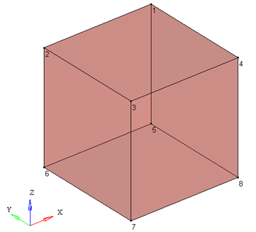
A 10 mm cube is modeled with a one element brick.
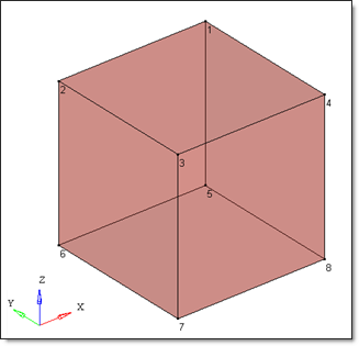
Fig 1: Geometry of the cube
RADIOSS Options Used
Boundary conditions depend on the test.
A scale factor of 0.1 (on time step for all elements) is used for “single elements models”.
Solid properties are:
| • | qa =1.1 and qb =0.05 (default values) |
| • | Iframe = 2 (co-rotational formulation) |
| • | Istrain is set to 1 (to post-treat strains). |
#---1----|----2----|----3----|----4----|----5----|----6----|----7----|----8----|----9----|---10----|
/PROP/SOLID/1
Concrete
# Isolid Ismstr Icpre Inpts Irot Iframe dn
1 0 0 0 0 2 0
# q_a q_b h
1.1 0.05 0
# dt_min Istrain
0 1
#---1----|----2----|----3----|----4----|----5----|----6----|----7----|----8----|----9----|---10----
|
Simulation Results and Conclusions
Curves
Test C000: Uniaxial Compression
The X displacement is fixed for nodes 2, 3, 6 and 7. A negative displacement is applied on the face defined by nodes 1, 4, 5 and 8.
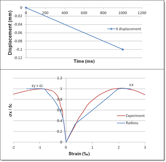
Fig 2: Uniaxial compression with RADIOSS (blue curves) and experiment (red curves)
Comments
| 1. | The stress/strain curve is made of three line segments. |
| 2. | After failure, the behavior obtained with RADIOSS curves (left) is perfectly plastic whereas there is experimentally a softening phenomenon (right). |
| 3. | The yield stress is obtained at σ = 0.337 fc for theoretical, numerical and experimental curves. |
Test T000: Uniaxial Tension
The X displacement is fixed for nodes 2, 3, 6 and 7. A positive displacement is applied on the face defined by nodes 1, 4, 5 and 8.
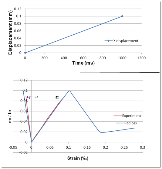
Fig 3: Uniaxial Tension with RADIOSS (blue curves) and experiment (red curves)
Comments
| 1. | Failure is modeled by stress and elastic modulus softening. |
| 2. | On the RADIOSS curve there is a residual stiffness in concrete after the softening: (1-Dsup)E |
| 3. | Dsup is set to 0.9 (default value = 0.99999). |
Test CC00: Biaxial Compression
The X displacement is fixed on nodes 2, 3, 6 and 7. The Y displacement is fixed on nodes 3, 4, 7 and 8.
A displacement is applied in X direction on the face described by nodes 1, 4, 5 and 8 and in Y direction on the face described by nodes 1, 2, 5 and 6.
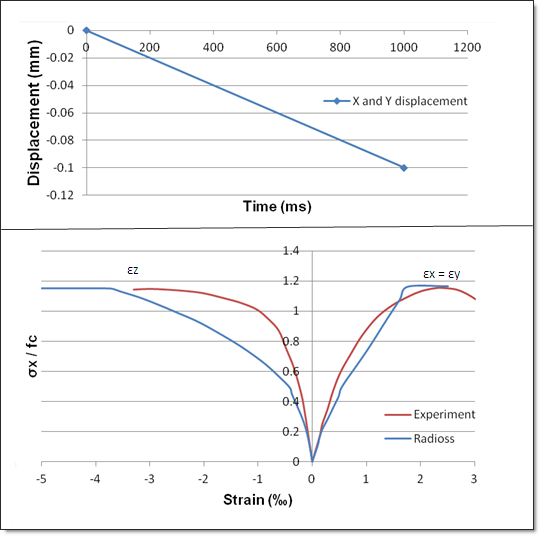
Fig 4: Biaxial Compression with RADIOSS (blue curves) and experiment (red curves)
Comments
| 1. | The yield stress is obtained at σ=0.197 fc for theoretical, numerical and experimental curves. |
| 2. | Failure mode is similar to uniaxial compression. |
Test CC01 Compression/Compression
The X displacement is fixed on nodes 2, 3, 6 and 7. The Z displacement is fixed on nodes 5, 6, 7 and 8.
A pressure load is applied in X direction on the face described by nodes 1, 4, 5 and 8 and in Z direction on the face described by nodes 1, 2, 3 and 4.
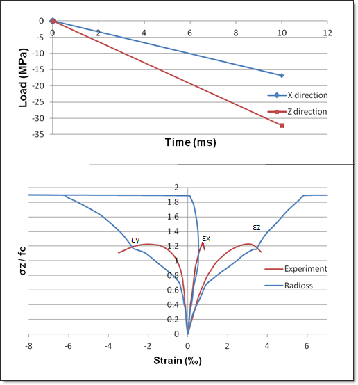
Fig 5: Compression/Compression with RADIOSS (blue curves) and experiment (red curves)
Comments
| 1. | Theoretical yield strength: 0.288 fc |
| 2. | Theoretical failure: 1.926 fc |
| 3. | Experimental failure: 1.22 fc |
| 4. | Theoretical and numerical results are the same, but different from experimental results; linear interpolation between the traction meridian and the compression meridian is too coarse for small confinement. |
TC01 Compression/Tension
X displacement is fixed on nodes 2, 3, 6 and 7.
Z displacement is fixed on nodes 5, 6, 7 and 8.
A pressure load is applied in X direction on the face described by nodes 1, 4, 5 and 8, and in Z direction on the face described by nodes 1, 2, 3 and 4.
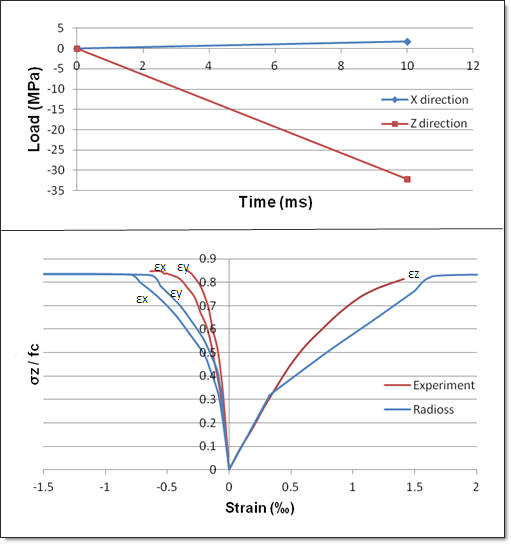
Fig 6: Compression/Tension with RADIOSS (blue curves) and experiment (red curves)
Comments
| 1. | Theoretical yield strength: 0.327 fc |
| 2. | Theoretical failure: 0.83 fc |
| 3. | Experimental failure: 0.85 fc |
| 4. | Theoretical, numerical and experimental results are the same. |
TC02 Compression/Tension
The X displacement is fixed on nodes 2, 3, 6 and 7. The Z displacement is fixed on nodes 5, 6, 7 and 8.
A pressure load is applied in X direction on the face described by nodes 1, 4, 5 and 8, and in Z direction on the face described by nodes 1, 2, 3 and 4.
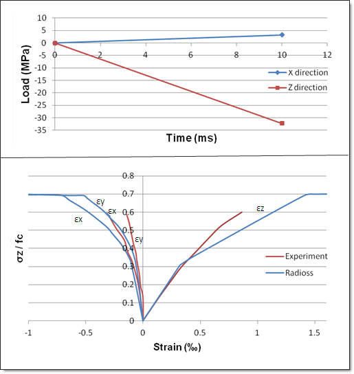
Fig 7: Compression/Tension with RADIOSS (blue curves) and experiment (red curves)
Comments
| 1. | Theoretical yield strength: 0.3 fc |
| 2. | Theoretical failure: 0.7 fc |
| 3. | Experimental failure: 0.6 fc |
| 4. | Theoretical and numerical results are the same, but slightly different from experimental results. |
TC03 Compression/Tension
The X displacement is fixed on nodes 2, 3, 6 and 7. The Z displacement is fixed on nodes 5, 6, 7 and 8.
A pressure load is applied in X direction on the face described by nodes 1, 4, 5 and 8, and in Z direction on the face described by nodes 1, 2, 3 and 4.
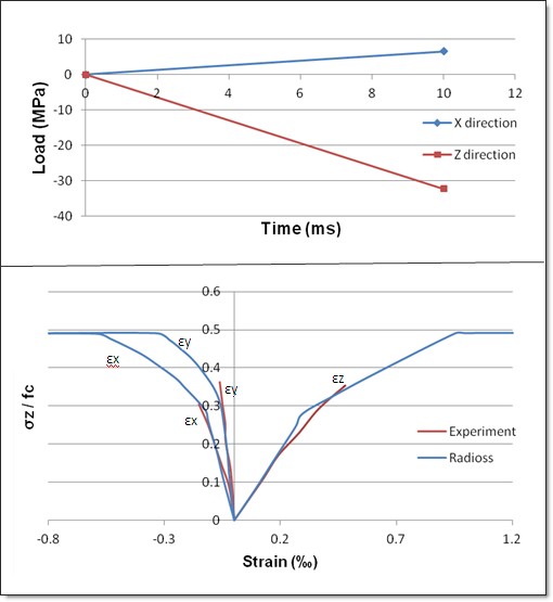
Fig 8: Compression/Tension with RADIOSS (blue curves) and experiment (red curves)
Comments
| 1. | Theoretical yield strength: 0.28 fc |
| 2. | Theoretical failure: 0.5 fc |
| 3. | Experimental failure: 0.35 fc |
| 4. | Theoretical and numerical results are the same, but different from experimental results. |
Test TRX00: Triaxial Meridian Shear
The X displacement is fixed on nodes 2, 3, 6 and 7. The Y displacement is fixed on nodes 3, 4, 7 and 8. The Z displacement is fixed on nodes 5, 6, 7 and 8.
A hydrostatic pressure of 51 MPa is applied on the sample.
A pressure load is applied in X direction on the face described by nodes 1, 4, 5 and 8, and in Z direction on the face described by nodes 1, 2, 3 and 4.
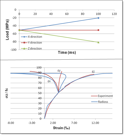
Fig 9: Triaxial Meridian Shear with RADIOSS (blue curves) and experiment (red curves)
Comments
| 1. | Theoretical yield strength: 64.3 MPa |
| 2. | Theoretical failure: 88.9 MPa |
| 3. | Experimental failure: 93 MPa |
Test TRX01: Triaxial Meridian Compression
The X displacement is fixed on nodes 2, 3, 6 and 7. The Y displacement is fixed on nodes 3, 4, 7 and 8. The Z displacement is fixed on nodes 5, 6, 7 and 8.
A hydrostatic pressure of 51 MPa is applied on the sample.
A pressure load is applied in X direction on the face described by nodes 1, 4, 5 and 8, in Y direction on the face described by nodes 1, 2, 5 and 6, and in Z direction on the face described by nodes 1, 2, 3 and 4.
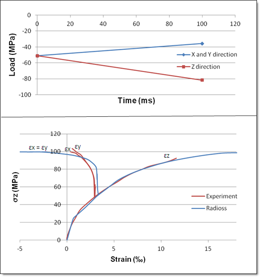
Fig 10: Triaxial Meridian Compression with RADIOSS (blue curves) and experiment (red curves)
Comments
| 1. | Theoretical yield strength: 68.4 MPa |
| 2. | Theoretical failure: 99.7 MPa |
| 3. | Experimental failure: 103 MPa |
| 4. | The behavior of the model under hydrostatic loading is elastic, whereas there are non-linearities experimentally. |
Test TRX02: Triaxial Meridian Compression
The X displacement is fixed on nodes 2, 3, 6 and 7. The Y displacement is fixed on nodes 3, 4, 7 and 8. The Z displacement is fixed on nodes 5, 6, 7 and 8.
An hydrostatic pressure of 51 MPa is applied on the sample.
A pressure load is applied in X direction on the face described by nodes 1, 4, 5 and 8, in Y direction on the face described by nodes 1, 2, 5 and 6, and in Z direction on the face described by nodes 1, 2, 3 and 4.
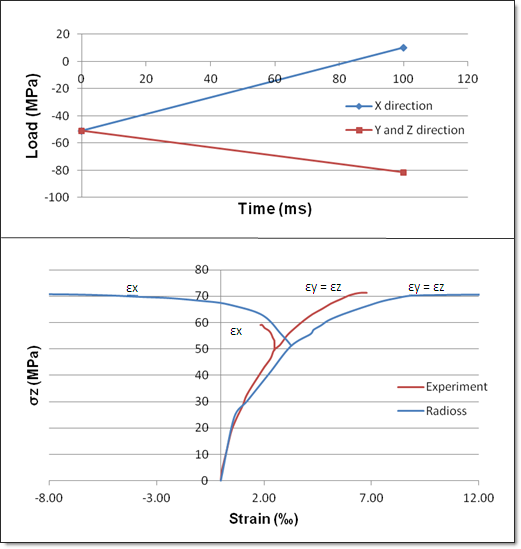
Fig 11: Triaxial Meridian Compression with RADIOSS (blue curves) and experiment (red curves)
Comments
| 1. | Theoretical yield strength: 57.9 MPa |
| 2. | Theoretical failure: 70.8 MPa |
| 3. | Experimental failure: 72 MPa |
Test BBX0: Tension-Compression-Tension Cycle without Reinforcement
A displacement is applied in the Z direction on the face defined by nodes 1, 2, 3 and 4 with a tension-compression-tension cycle as shown below:
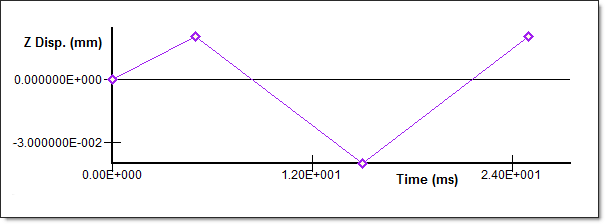
Fig 12: Velocity imposed
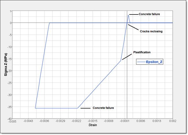
Fig 13: Cycle without reinforcement
This test illustrates the behavior of the model LAW24:
| • | Failure, damage and cracks reopening |
| • | Plastification and hardening |
| • | Residual plastic deformation |
Test BBX1: Tension-Compression-Tension Cycle with Reinforcement
A velocity is set among the Z direction on the face defined by nodes 1, 2, 3 and 4 with a tension-compression-tension cycle, as shown below:
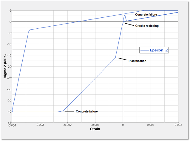
Fig 14: Cycle with reinforcement
Comments
| 1. | Steel reinforcement improves compressive and tensile strength by 5 MPa compared to the same model without steel reinforcement. |
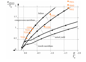
Von Mises / Pressure Curves
The following von Mises/Pressure curves show the different areas described by tensile and compressive tests.
Each orange point corresponds to the failure point of the model considered.
fc is the uniaxial compressive strength.
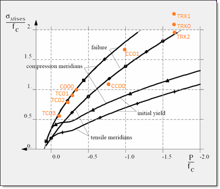
Fig 15: von Mises/Pressure curves
Conclusion
Under complex loading, concrete mechanic behavior between RADIOSS simulation, theory and experiments are demonstrated. With three kinds of tests, the mechanic behavior of concrete can be well characterized using LAW24.
References
[1] A non-uniform hardening plasticity model for concrete materials, Mechanics of Materials, D.J. Han and W.F. Chen, 1984.
[2] Behavior of Concrete under Biaxial Stresses, Journal of the Engineering Mechanics Division, ASCE, V. 99, No. 4, pp. 853-866u, LKupfer, B., and Gerstle, K., 1973.


