46.2 - Euler Formulation |

|

|

|

|
|
46.2 - Euler Formulation |

|

|

|

|
TitleCylinder Expansion Test with Euler formulation |
|
||||||||
Number46.2 |
|||||||||
Brief DescriptionDetonation is initiated at the bottom of the explosive. Radial expansion of the cylinder is measured and compared to experimental data. |
|||||||||
Keywords
|
|||||||||
RADIOSS Options
|
|||||||||
Input FileCylinder Test: <install_directory>/demos/hwsolvers/radioss/46_TNT_Cylinder_Expansion_Test/Euler/* |
|||||||||
Technical / Theoretical LevelAdvanced |
|||||||||
The purpose of this example is to show how to simulate the cylinder expansion test and compare the simulation result to experimental data.
A OFHC copper cylinder (1.53cm diameter, 0.26cm thickness, 30.5cm height) is filled with an explosive (TNT). Detonation is initiated at the bottom of the explosive. Radial expansion is measured at a length of 8*D cm. With an Euler formulation, the air has to be modeled to measure radial expansion.
Since this problem is axisymmetric, only a quarter of the cylinder is modeled.

Fig 1: Problem description for cylinder test
Units: cm, µs, g, Mbar
Using the Multi-Material Solid, Liquid, and Gas material law (/MAT/LAW51), the copper cylinder material has the following characteristics:
| • | Initial density = 8.96 |
| • | Initial pressure C0mat1 = 1e-6 |
| • | Hydrodynamic coefficients: |
| ▪ | C1mat1 = 1.38 |
| ▪ | C2mat1 = 1.372 |
| ▪ | C4mat1 = 0.87 |
| ▪ | C5mat1 = 0.87 |
| • | Elastic shear modulus G1mat1 = 0.519 |
| • | Yield stress amat1 = 0.9e-3 |
| • | Plastic yield factor bmat1 = 0.292e-2 |
| • | Plastic yield exponent nmat1 = 0.31 |
| • | Plastic strain rate factor cmat1 = 0.025 |
| • | Plastic reference strain rate |
| • | Thermal exponent mmat1 = 1.09 |
| • | Specific heat Rhocvmat1 = 3.461e-5 |
| • | Tmelt = 1656 |
#---1----|----2----|----3----|----4----|----5----|----6----|----7----|----8----|----9----|---10----| /MAT/LAW51/1 Copper
# Iform 10 # P_ext NU Nu_Vol 0 0 0 # ALPHA0_mat1 RHO0_mat1 E0_mat1 Pmin_mat1 C0_mat1 1 8.96 0 0 1E-6 # C1_mat1 C2_mat1 C3_mat1 C4_mat1 C5_mat1 1.38 1.372 0 .87 .87 # G1_mat1 a_mat1 b_mat1 n_mat1 .519 9E-4 .00292 .31 # c_mat1 EPSILON_DOT0_mat1 .025 1E-6 # m_mat1 T0_mat1 Tmelt_mat1 Tlim_mat1 Rhocv_mat1 1.09 0 1656 0 3.461E-5 # Epspmax_mat1 sigma_max_mat1 KA_mat1 KB_mat1 0 0 0 0 # ALPHA0_mat2 RHO0_mat2 E0_mat2 Pmin_mat2 C0_mat2 0 .0012 2.5E-6 -1E-20 0 # C1_mat2 C2_mat2 C3_mat2 C4_mat2 C5_mat2 0 0 0 .4 .4 # G1_mat2 a_mat2 b_mat2 n_mat2 0 0 0 0 # c_mat2 EPSILON_DOT0_mat2 0 0 # m_mat2 T0_mat2 Tmelt_mat2 Tlim_mat2 Rhocv_mat2 0 0 0 0 0 # Epspmax_mat2 sigma_max_mat2 KA_mat2 KB_mat2 0 0 0 0 # ALPHA0_mat3 RHO0_mat3 E0_mat3 Pmin_mat3 C0_mat3 0 0 0 0 0 # C1_mat3 C2_mat3 C3_mat3 C4_mat3 C5_mat3 0 0 0 0 0 # G1_mat3 a_mat3 b_mat3 n_mat3 0 0 0 0 # c_mat3 EPSILON_DOT0_mat3 0 0 # m_mat3 T0_mat3 Tmelt_mat3 Tlim_mat3 Rhocv_mat3 0 0 0 0 0 # Epspmax_mat3 sigma_max_mat3 KA_mat3 KB_mat3 0 0 0 0 # ALPHA0_mat4 RHO0_mat4 E0_mat4 Pmin_mat4 C0_mat4 0 1.63 .07 -1E-20 1E-6 # A B R1 R2 W 3.712 .0323 4.15 .95 .3 # D PCJ C1_mat4 .693 .21 .036 /EULER/MAT/1 # Modif. factor. 0 #---1----|----2----|----3----|----4----|----5----|----6----|----7----|----8----|----9----|---10----| |
Using Multi-Material Solid, Liquid, and Gas material law (/MAT/LAW51), the TNT material has the following characteristics:
| • | Initial density = 1.63 |
| • | Explosive cavitation pressure Pminmat4 = -1e-20 |
| • | Initial explosive pressure C0mat4 = 1e-6 |
| • | Explosive coefficient B1 = 3.712 |
| • | Explosive coefficient B2 = 0.0323 |
| • | Explosive coefficient R1 = 4.15 |
| • | Explosive coefficient R2 = 0.95 |
| • | Explosive coefficient |
| • | Explosive coefficient C1mat4 = 0.036 |
Chapman Jouget parameters compute detonation time and burn fraction evolution:
| • | Detonation velocity D = 0.693 |
| • | Chapman Jouguet pressure PCJ = 0.21 |
| • | Initial explosive energy per unit initial volume E0mat4 = 0.07 |
#---1----|----2----|----3----|----4----|----5----|----6----|----7----|----8----|----9----|---10----| /MAT/LAW51/2 TNT
# Iform 10 # P_ext NU Nu_Vol 0 0 0 # ALPHA0_mat1 RHO0_mat1 E0_mat1 Pmin_mat1 C0_mat1 0 8.96 0 0 1E-6 # C1_mat1 C2_mat1 C3_mat1 C4_mat1 C5_mat1 1.38 1.372 0 .87 .87 # G1_mat1 a_mat1 b_mat1 n_mat1 .519 9E-4 .00292 .31 # c_mat1 EPSILON_DOT0_mat1 .025 1E-6 # m_mat1 T0_mat1 Tmelt_mat1 Tlim_mat1 Rhocv_mat1 1.09 0 1656 0 3.461E-5 # Epspmax_mat1 sigma_max_mat1 KA_mat1 KB_mat1 0 0 0 0 # ALPHA0_mat2 RHO0_mat2 E0_mat2 Pmin_mat2 C0_mat2 0 .0012 2.5E-6 -1E-20 0 # C1_mat2 C2_mat2 C3_mat2 C4_mat2 C5_mat2 0 0 0 .4 .4 # G1_mat2 a_mat2 b_mat2 n_mat2 0 0 0 0 # c_mat2 EPSILON_DOT0_mat2 0 0 # m_mat2 T0_mat2 Tmelt_mat2 Tlim_mat2 Rhocv_mat2 0 0 0 0 0 # Epspmax_mat2 sigma_max_mat2 KA_mat2 KB_mat2 0 0 0 0 # ALPHA0_mat3 RHO0_mat3 E0_mat3 Pmin_mat3 C0_mat3 0 0 0 0 0 # C1_mat3 C2_mat3 C3_mat3 C4_mat3 C5_mat3 0 0 0 0 0 # G1_mat3 a_mat3 b_mat3 n_mat3 0 0 0 0 # c_mat3 EPSILON_DOT0_mat3 0 0 # m_mat3 T0_mat3 Tmelt_mat3 Tlim_mat3 Rhocv_mat3 0 0 0 0 0 # Epspmax_mat3 sigma_max_mat3 KA_mat3 KB_mat3 0 0 0 0 # ALPHA0_mat4 RHO0_mat4 E0_mat4 Pmin_mat4 C0_mat4 1 1.63 .07 -1E-20 1E-6 # A B R1 R2 W 3.712 .0323 4.15 .95 .3 # D PCJ C1_mat4 .693 .21 .036 /EULER/MAT/2 # Modif. factor. 0 #---1----|----2----|----3----|----4----|----5----|----6----|----7----|----8----|----9----|---10----| |
Using the Multi-Material Solid, Liquid, and Gas material law (/MAT/LAW51), the Air material has the following characteristics:
| • | Initial density = 0.0012 |
| • | Initial energy per unit initial volume E0mat2 = 2.5e-6 |
| • | Hydrodynamic cavitation pressure Pminmat2 = -1e-20 |
| • | Hydrodynamic coefficient C4mat2 = 0.4 |
| • | Hydrodynamic coefficient C5mat2 = 0.4 |
#---1----|----2----|----3----|----4----|----5----|----6----|----7----|----8----|----9----|---10----| /MAT/LAW51/3 Air
# Iform 10 # P_ext NU Nu_Vol 0 0 0 # ALPHA0_mat1 RHO0_mat1 E0_mat1 Pmin_mat1 C0_mat1 0 8.96 0 0 1E-6 # C1_mat1 C2_mat1 C3_mat1 C4_mat1 C5_mat1 1.38 1.372 0 .87 .87 # G1_mat1 a_mat1 b_mat1 n_mat1 .519 9E-4 .00292 .31 # c_mat1 EPSILON_DOT0_mat1 .025 1E-6 # m_mat1 T0_mat1 Tmelt_mat1 Tlim_mat1 Rhocv_mat1 1.09 0 1656 0 3.461E-5 # Epspmax_mat1 sigma_max_mat1 KA_mat1 KB_mat1 0 0 0 0 # ALPHA0_mat2 RHO0_mat2 E0_mat2 Pmin_mat2 C0_mat2 1 .0012 2.5E-6 -1E-20 0 # C1_mat2 C2_mat2 C3_mat2 C4_mat2 C5_mat2 0 0 0 .4 .4 # G1_mat2 a_mat2 b_mat2 n_mat2 0 0 0 0 # c_mat2 EPSILON_DOT0_mat2 0 0 # m_mat2 T0_mat2 Tmelt_mat2 Tlim_mat2 Rhocv_mat2 0 0 0 0 0 # Epspmax_mat2 sigma_max_mat2 KA_mat2 KB_mat2 0 0 0 0 # ALPHA0_mat3 RHO0_mat3 E0_mat3 Pmin_mat3 C0_mat3 0 0 0 0 0 # C1_mat3 C2_mat3 C3_mat3 C4_mat3 C5_mat3 0 0 0 0 0 # G1_mat3 a_mat3 b_mat3 n_mat3 0 0 0 0 # c_mat3 EPSILON_DOT0_mat3 0 0 # m_mat3 T0_mat3 Tmelt_mat3 Tlim_mat3 Rhocv_mat3 0 0 0 0 0 # Epspmax_mat3 sigma_max_mat3 KA_mat3 KB_mat3 0 0 0 0 # ALPHA0_mat4 RHO0_mat4 E0_mat4 Pmin_mat4 C0_mat4 0 1.63 .07 -1E-20 1E-6 # A B R1 R2 W 3.712 .0323 4.15 .95 .3 # D PCJ C1_mat4 .693 .21 .036 /EULER/MAT/3 # Modif. factor. 0 #---1----|----2----|----3----|----4----|----5----|----6----|----7----|----8----|----9----|---10----| |
Using the Multi-Material Solid, Liquid, and Gas material law (/MAT/LAW51), the Boundary material has the following characteristics:
#---1----|----2----|----3----|----4----|----5----|----6----|----7----|----8----|----9----|---10----| /MAT/LAW51/4 Boundary # Iform 3 # ALPHA_1 RHO_01 E_01 P_min1 C_01 0 8.96 0 0 1E-6
# ALPHA_2 RHO_02 E_02 P_min2 C_02 1 .0012 2.5E-6 -1E-20 1E-6
# ALPHA_3 RHO_03 E_03 P_min3 C_03 0 0 0 0 0
/EULER/MAT/4 # Modif. factor. 0 #---1----|----2----|----3----|----4----|----5----|----6----|----7----|----8----|----9----|---10----| |
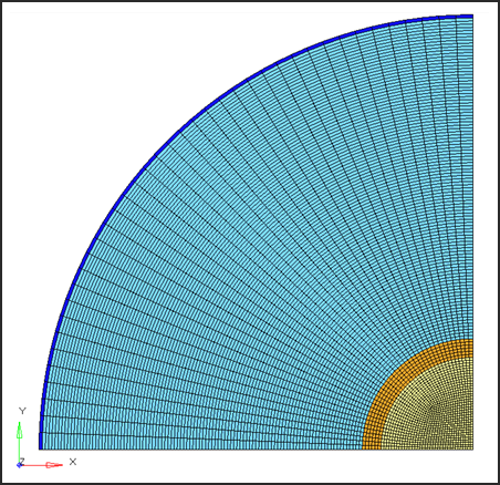
A 3D mesh is made of brick elements. The element size for the copper cylinder is approximately of 0.035 cm x 0.035 cm x 0.035 cm.
The mesh is dragged along the z direction (z = 30.5 cm). It is important to have no discontinuity in element volume in order to ensure a good propagation of detonation wave and shock wave.
Units: cm, µs, g, Mbar

Fig 2: Model mesh
Due to the symmetries of the model, a quarter of the cylinder is modeled. Boundary conditions are set on the yOz plan at x = 0 (Tx = 0) and on the xOz plan at y = 0 (Ty = 0) to simulate the symmetry.
A planar detonation wave is defined at the bottom of the cylinder. A scale factor of 0.5 (on time step for all elements) is used for this type of application.
In solid properties, qa =1.1 and qb =0.05. These values must be set to 0 for the Lagrange formulation.
| • | Isolid is set to 0 for TNT and copper solid properties. |
#---1----|----2----|----3----|----4----|----5----|----6----|----7----|----8----|----9----|---10----| /PROP/SOLID/2 copper # Isolid Ismstr Icpre Inpts Itetra Iframe dn 0 0 0 0 0 0 0 # q_a q_b h LAMBDA_V MU_V 1.1 .05 0 0 0 # dt_min istrain IHKT 0 0 0 #---1----|----2----|----3----|----4----|----5----|----6----|----7----|----8----|----9----|---10----| |
#---1----|----2----|----3----|----4----|----5----|----6----|----7----|----8----|----9----|---10----| /PROP/SOLID/1 TNT # Isolid Ismstr Icpre Inpts Itetra Iframe dn 0 0 0 0 0 0 0 # q_a q_b h LAMBDA_V MU_V 1.1 .05 0 0 0 # dt_min istrain IHKT 0 0 0 #---1----|----2----|----3----|----4----|----5----|----6----|----7----|----8----|----9----|---10----| |
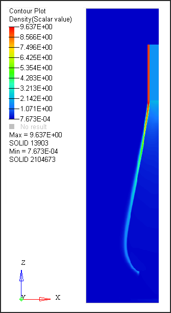
The following figure displays the variation of density in the cylinder, explosive and air.

Fig. 3: Density distributed in copper and TNT at time = 33µs.
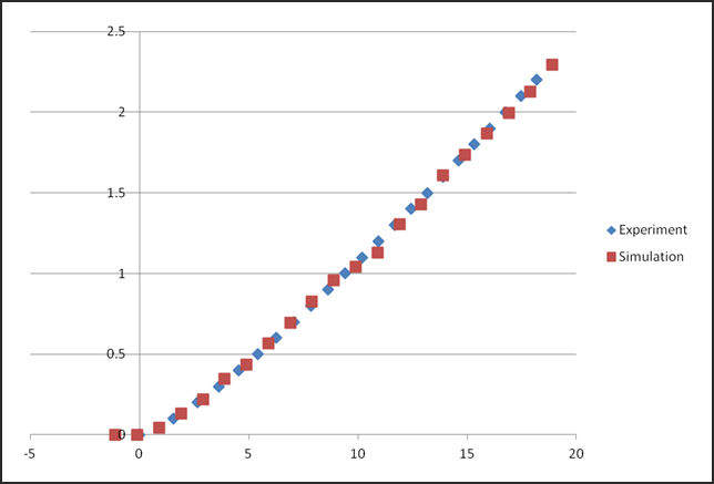
The following diagram shows the comparison between the experimental and simulation measurement of radial expansion. The displacement values are estimated on the animations using the density contour.

Fig. 4: Comparison between experimental results and simulation results
Good correlation between experimental and simulation results. A thinner meshing could improve the correlation between simulation and experimental curves.
[1] Adiabatic Expansion of high explosive detonation products, LANL, Wilkins (1969)
[2] A Constitutive model and data for metals subjected to large strains, high strain rates and high temperatures, Gordon R. Johnson, William H. Cook