Block Format Keyword
/IMPVEL - Imposed Velocities
Description
Defines imposed velocities on a group of nodes.
Format
(1)
|
(2)
|
(3)
|
(4)
|
(5)
|
(6)
|
(7)
|
(8)
|
(9)
|
(10)
|
/IMPVEL/impvel_ID/unit_ID
|
impvel_title
|
fct_IDT
|
Dir
|
skew_ID
|
sens_ID
|
grnd_ID
|
frame_ID
|
icoor
|
|
|
|
Ascalex
|
FscaleY
|
Tstart
|
Tstop
|
|
|
Field
|
Contents
|
SI Unit Example
|
impvel_ID
|
Imposed velocity block identifier
(Integer, maximum 10 digits)
|
|
unit_ID
|
Optional unit identifier
(Integer, maximum 10 digits)
|
|
impvel_title
|
Imposed velocity block title
(Character, maximum 100 characters)
|
|
fct_IDT
|
Time function identifier
(Integer)
|
|
Dir
|
Direction: X, Y, and Z in translation; XX, YY, and ZZ in rotation
(Text)
|
|
skew_ID
|
Skew identifier
≠ 0: the imposed velocity is computed in the global frame and projected onto the local skew.
(Integer)
|
|
sens_ID
|
Sensor identifier
≠ 0 (sensor activated): the imposed velocity is applied after sensor activation. The time function is shifted by the sensor activation time.
(Integer)
|
|
grnd_ID
|
Node group on which the imposed velocity is applied
(Integer)
|
|
frame_ID
|
Frame identifier
≠ 0: the imposed velocity is computed and applied in the local frame.
(Integer)
|
|
icoor
|
Coordinate system usage type
(Integer)
= 0: Cartesian coordinates
= 1: Cylindrical coordinates
|
|
Ascalex
|
Abscissa (time) scale factor for fct_IDT
Default = 1.0 (Real)
|

|
FscaleY
|
Ordinate (velocity) scale factor for fct_IDT
Default = 1.0 (Real)
|

|
Tstart
|
Start time
(Real)
|
|
Tstop
|
Stop time
Default = 1030 (Real)
|
|
|
| 1. | The velocity direction must be right justified in the ten characters of field number 2. |
| 2. | If a velocity is imposed in a frame (frame_ID ≠ 0), the frame nodes must not have an imposed velocity themselves. |
| 3. | If Tstart and Tstop are specified, the velocity is imposed between these times. However, in this case, the time vs. velocity function is not shifted to begin at Tstart. |
| 4. | The AscaleX and FscaleY are used to scale the abscissa (time) and ordinate (velocity). |
The actual load function value is calculated as following:
| 5. | SKEW and FRAME cannot be defined together. This is SKEW or FRAME. |
| 6. | If icoor=1, the directions X, Y, and Z (resp. XX, YY, and ZZ) refer to translations along (resp. rotations around) the radial direction (r), azimuthal angular direction ( ) and longitudinal direction (Z) (refer to /SKEW and /FRAME). ) and longitudinal direction (Z) (refer to /SKEW and /FRAME). |
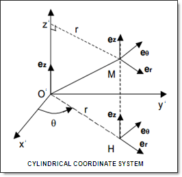
| 7. | If icoor=1 when imposing the translational velocity in the radial, resp. the azimuthal direction, the velocity of the node is set so that: |
with 
|
See Also:
Implicit Features and Compatibility Information
Skew and Frame (/SKEW & /FRAME)
Example 2 - Snap-through Roof
Example 6 - Fuel Tank
Example 8 - Hopkinson Bar
Example 10 - Bending
Example 11 - Tensile Test
Example 15 - Gears
Example 17 - Box Beam
Example 24 - Laminating
Example 25 - Spring-back
Example 26 - Ruptured Plate


