Example 26 - Ruptured Plate |

|

|

|

|
|
Example 26 - Ruptured Plate |

|

|

|

|
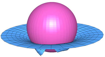
Failure of a circular plate subjected to the impact of an infinite rigid sphere is studied. Material models, with or without a dedicated failure criteria, are compared. The new failure criteria available adds to the simple rupture models existing in such material laws as Law 2 and Law 27. The study is divided into three parts:
| • | Rupture using a damage model in Law 27 |
| • | Failure using the Johnson-Cook model |
| • | Advantage of Forming Limit Diagram as a failure model |
The sensitivity of the results for the different failure models is demonstrated.
TitleRuptured plate |
|
||||||||||
Number26.1 |
|||||||||||
Brief DescriptionA metallic thick plate is perforated by a rigid sphere. Simulation of the rupture uses different failure models. |
|||||||||||
Keywords
|
|||||||||||
RADIOSS Options
|
|||||||||||
Input FileLaw 2 without failure: <install_directory>/demos/hwsolvers/radioss/26_Ruptured_plate/Law2/Without_FAIL/LAW2* Johnson failure: <install_directory>/demos/hwsolvers/radioss/26_Ruptured_plate/Law2/JOHNSON_model/.../FAILURE_JOHNSON* FLD failure: <install_directory>/demos/hwsolvers/radioss/26_Ruptured_plate/Law2/FLD_model/Ishell=1_without_epsmax/.../FAILURE_FLD* Law 27: <install_directory>/demos/hwsolvers/radioss/26_Ruptured_plate/Law27/LAW27* |
|||||||||||
Technical / Theoretical LevelAdvanced |
|||||||||||
The purpose of this example is to model the perforation of a thick plate using a rigid sphere. The simulations are performed using different failure models:
| • | Damage model integrated in the elasto-plastic material law (/MAT/LAW27) |
| • | Johnson-Cook failure model, in addition to the elasto-plastic material law (/MAT/LAW2) |
| • | Failure model using the generic Forming Limit Diagram (FLD), in addition to the elasto-plastic material law 2 |
Numerical results are not compared with experimental data. However, this example proposes different approaches to take account of failure.
A 3 mm thick plate is impacted at its midpoint by a 12.7 mm diameter sphere with an imposed velocity of 1 ms-1.
Units: mm, ms, g, N, MPa.
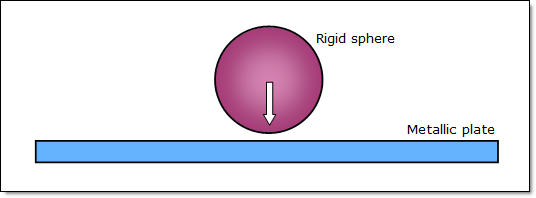
Fig 1: Problem description.
The material undergoes an isotropic elasto-plastic behavior which can be reproduced by a Johnson-Cook model, independently of the failure model: ![]() .
.
Material properties are:
| • | Young’s modulus: 71000 MPa |
| • | Poisson’s ratio: 0.3 |
| • | Density: 2.8 x 10⁻³ g/mm3 |
| • | Yield stress: 290 MPa |
| • | Hardening parameter: 562.3 MPa |
| • | Hardening exponent: 0.63 |
The maximum stress and the failure plastic strain are considered in the failure modeling section. The strain rate effect is not taken into account in this example.
The plate is meshed with 4-node shell elements.
The shell properties (Type 1) are:
| • | 5 integration points (progressive plastification) |
| • | Belytschko elasto-plastic hourglass formulation (Ishell = 3) |
| • | Iterative plasticity for plane stress (Iplas = 1) |
| • | Thickness is constant (Ithick = 0) |
| • | Initial thickness is uniform, equal to 3 mm |
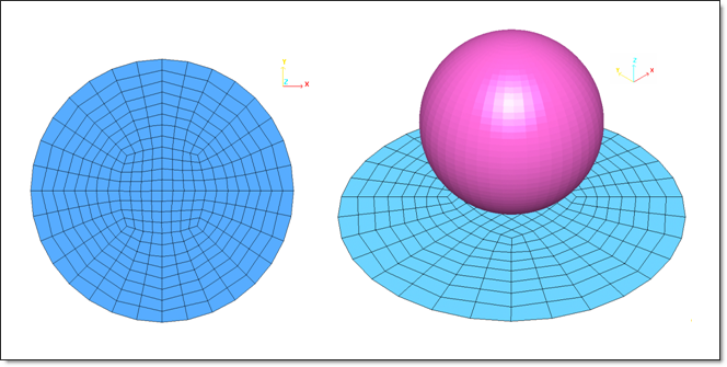
Fig 2: Mesh of the metallic plate with the initial rigid sphere position.
A sphere with non-zero mass is considered as a rigid body, modeled by a rigid sphere of 12.7 mm diameter. Slave nodes include the plate part.
Here in this example, non-zero mass (5g) in /RWALL will keep energy balance. If mass =0, then 99% energy error is received. This is because you have external work done by the rigid wall and this external work is proportional to the mass of the rigid wall. But if the mass is zero, then the external works is also zero. The loss of external work will lead to bad energy balance.
A constant imposed velocity of -1.0 ms-1 in the Z-direction is applied on the rigid sphere via the ID 4067 master node. Its displacement is proportionally linked to time.
Boundaries of the plate are clamped, as shown in Fig 3.
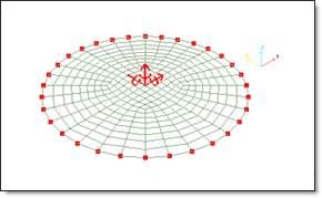
Fig 3: Side fixed in X, Y, Z translations and X, Y, Z rotations.
Law 27 is used to simulate material damage following a Johnson-Cook plasticity law. Thus, a damage model is incorporated into the material law to take into account the damage evolution with stress decreasing up to element rupture.
The damage parameters are:
| • | Tensile rupture strain |
| • | Maximum strain |
| • | Maximum damage factors dmax1: this value should be kept at its default value (0.999). |
| • | Failure strain |
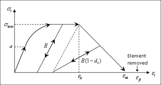
Fig 4: Stress/strain curve for damage affected material (with i=1,2)
For the first principal direction: |
For the second principal direction: |
|
|
|
|
|
|
dmax1 = 0.999 |
dmax2 = 0.999 |
The maximum stress and the failure plastic strain are activated:
| • |
| • |
The element is removed if one layer (one integration point) of the element reaches the failure tensile strain.
For further information about this law, refer to the RADIOSS Theory Manual and RADIOSS User's Guide.
The elasto-plastic behavior of the material is defined using the Johnson-Cook law (/MAT/LAW2), with or without damage (![]() max and
max and ![]() max). The failure model is independent from the material law and the hardening model.
max). The failure model is independent from the material law and the hardening model.
The Johnson-Cook failure model is defined using /FAIL/JOHNSON in the input deck.
The model uses cumulative damage to compute failure.
![]()
![]()
where,
D refers to the current damage (failure if D = 1)
![]() is the normalized mean stress
is the normalized mean stress
![]() is the increment of plastic strain during the loading increment
is the increment of plastic strain during the loading increment
D1, D2 and D3 are the first three parameters
The strain rate and thermo-plastic effects are not taken into account in this example. Therefore, only three parameters are required (D1, D2 and D3).
Two cases are considered:
| • | The maximum stress and the failure plastic strain are not taken into account. |
| • | In addition to the Johnson-Cook failure model, the maximum stress and the failure plastic strain are activated. |
Two failure approaches are also investigated:
| • | Shell element is deleted if damage D > 1, for one layer (Ifail_sh set to 1) |
| • | The layer stress tensor is set to zero and the shell element is deleted if damage D > 1, for all layers (Ifail_sh set to 2). |
Therefore, the four simulations performed are shown in the following table:
|
Ifail_sh = 1 |
Ifail_sh = 2 |
||
/FAIL
|
only /FAIL |
/FAIL
|
only /FAIL |
|
Johnson-Cook failure model |
D1 = 0.11 D2 = 0.08 D3 = -1.5
|
D1 = 0.09 D2 = 0.08 D3 = -1.5 |
D1 = 0.11 D2 = 0.08 D3 = -1.5
|
D1 = 0.09 D2 = 0.08 D3 = -1.5 |
For further information about this failure model, refer to the RADIOSS Theory Manual and the RADIOSS User's Guide.
This failure model uses the generic forming limit diagram, defined for the given material. The curve is expressed in the area of principal strains (max and mini strains) and defines the failure zone.
An input curve and the flag Ifail_sh (same as Johnson-Cook model) are required. However, the results obtained using Ifail_sh = 1 and Ifail_sh = 2 are very similar and only if Ifail_sh = 1 is presented.
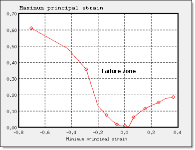
Two failure modes can be simulated by adjusting the diagram. Shells elements are deleted if one layer is in the failure zone.
| Explosive Perforation (Hole Creation) | Perforation by Shell Tearing |
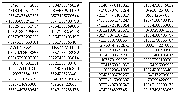
| Curve 1 | Curve 2 |
For further information about this failure model, see the RADIOSS User's Guide.
The failure simulations considered in the example are:
Incorporated damage model + |
|||||
Material law 27 |
|
||||
|
|
||||
Material law 2 |
|
||||
Law 2 + /FAIL |
Ifail_sh = 1 |
Ifail_sh = 2 |
|||
/FAIL
|
only /FAIL |
/FAIL
|
only /FAIL |
||
Johnson failure model |
|
|
|
|
|
FLD failure model |
FLD 1 |
|
|
|
|
FLD 2 |
|
|
|
|
|
Engine file:
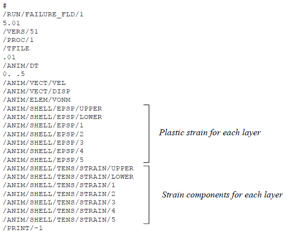
In the /DEF_SHELL option defined in the input desk, the Istrain flag must be set to 1 for computing strains in view of post-processing.
During simulation, failure of the elements can be checked in the output file runname_0001.out.
| • | Example of output file (extract): |
[…]
3869 0.5145 0.1330E-03 SHELL 159 0.0% 2451. 0.1692 2.336 0.0000E+00 0.0000E+00
3870 0.5147 0.1330E-03 SHELL 159 0.0% 2452. 0.1697 2.335 0.0000E+00 0.0000E+00
-- RUPTURE OF SHELL ELEMENT NUMBER 151
-- RUPTURE OF SHELL ELEMENT NUMBER 151
3871 0.5148 0.1330E-03 SHELL 159 0.0% 2453. 0.1694 2.361 0.0000E+00 0.0000E+00
3872 0.5149 0.1330E-03 SHELL 159 0.0% 2452. 0.7397 3.424 0.0000E+00 0.0000E+00
3873 0.5151 0.1330E-03 SHELL 159 0.0% 2446. 3.288 6.740 0.0000E+00 0.0000E+00
3874 0.5152 0.1330E-03 SHELL 159 0.0% 2443. 5.818 8.481 0.0000E+00 0.0000E+00
-- RUPTURE OF SHELL ELEMENT NUMBER 169
-- RUPTURE OF SHELL ELEMENT NUMBER 169
-- RUPTURE OF SHELL ELEMENT NUMBER 192
-- RUPTURE OF SHELL ELEMENT NUMBER 192
3875 0.5153 0.1330E-03 SHELL 159 0.0% 2443. 6.888 8.419 0.0000E+00 0.0000E+00
3876 0.5155 0.1330E-03 SHELL 159 0.0% 2443. 7.988 8.214 0.0000E+00 0.0000E+00
3877 0.5156 0.1330E-03 SHELL 159 0.0% 2437. 12.35 9.924 0.0000E+00 0.0000E+00
3878 0.5157 0.1330E-03 SHELL 159 0.0% 2430. 17.44 11.89 0.0000E+00 0.0000E+00
3879 0.5159 0.1329E-03 SHELL 159 0.0% 2425. 21.28 13.40 0.0000E+00 0.0000E+00
3880 0.5160 0.1329E-03 SHELL 159 0.0% 2421. 23.82 14.56 0.0000E+00 0.0000E+00
-- RUPTURE OF SHELL ELEMENT NUMBER 153
-- RUPTURE OF SHELL ELEMENT NUMBER 153
3881 0.5161 0.1329E-03 SHELL 159 0.0% 2419. 25.85 15.13 0.0000E+00 0.0000E+00
[…]
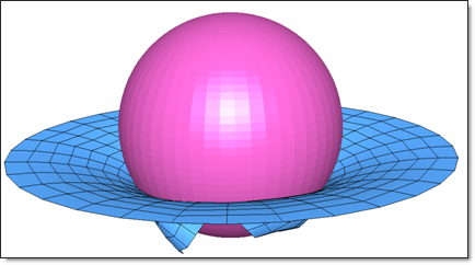
Fig 6: Perforation of the plate by the rigid sphere at 5 ms (case: Johnson-Cook failure model without failure plastic strain, Ifail_sh=2).
The following table compares the results provided by simulations in terms of plate deformation, hole dimension, residual shells, etc.
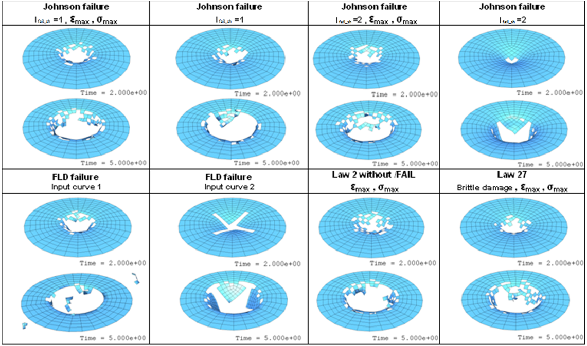
The rupture of a circular plate, due to the impact of a rigid sphere was studied and several failure models with different simulation parameters were compared. The results obtained highlight the sensitivity of the numerical models to simulate the failure.
Laws 2 and 27, with or without the failure models were compared. The comparison shows that the results are quite similar when coherent simulation parameters are used.