|
»Click here to display Table of Contents«
|

Example 15 - Gears |

|

|

|

|
|
Example 15 - Gears |
|
|
|

|
|
»Click here to display Table of Contents«
|
Example 15 - Gears |
|
|
|
|
|
Example 15 - Gears |
|
|
|
|
The main purpose of this example is to study how to represent a quadratic contact. Two different interfaces are compared:
| • | Type 16 interface (node to surface) |
| • | Type 17 interface (surface to surface) |
Moreover, 20-node brick and 16-node shell elements are used for the mesh to represent the curvature of the teeth. Constant acceleration is also applied to the gear using constant initial rotation and an imposed velocity.
Finally the results of the contact force show that the type 16 interface is more adaptable than a type 17 interface.
TitleSimple gears |
|
||||||||||
Number15.1 |
|||||||||||
Brief DescriptionThe problem studied is a twin gear having an identical pitch diameter and straight teeth. |
|||||||||||
Keywords
|
|||||||||||
RADIOSS Options
|
|||||||||||
Input FileInterface_type16: <install_directory>/demos/hwsolvers/radioss/15_Gears/Inter16/DIF24416* Interface_type17: <install_directory>/demos/hwsolvers/radioss/15_Gears/Inter17/DIF24416* |
|||||||||||
Technical / Theoretical LevelAdvanced |
|||||||||||
The purpose of this example is to illustrate the use of quadratic contact via node-surface and surface-to-surface interfaces of types 16 and 17.
The following study shows a gear example using interface type 16 and type 17. The finite elements used to model this gear are the thick SHELL16 elements and the quadratic BRICK20 elements. In the first stage the interface type 16 is used to model contact between the teeth. Then, interface type 17 is used to manage a surface-to-surface contact.
The gear system is turning with a constant acceleration (![]() = 0.002 rad/ms2). The acceleration is applied to both of the gears. It is assumed that contact between the teeth does not generate any friction.
= 0.002 rad/ms2). The acceleration is applied to both of the gears. It is assumed that contact between the teeth does not generate any friction.
Steel characteristic (elastic /MAT/LAW2) are:
| • | Young Modulus: 210000 MPa |
| • | Density: 7.8x10-03 g/mm3 |
| • | Poisson’s coefficient: 0.29 |
| • | Number of teeth: Z =19 |
| • | Diametric pitch: P = 1/mo = 1/40 |
| • | Pressure angle: ao = 20 degrees |
The following parameters are calculated as:
| Pitch diameter: | Dp = mo * Z, then Dp = 760 mm |
| Root diameter: | Db = mo * cos(ao), then Db = 714.17 mm |
| Addendum: | ha = mo, then ha = 40 mm |
| Dedendum: | hf = 1.25 * mo, then hf = 50 mm |
| Circular pitch: | p = PI * mo, then p = 125.66 mm |
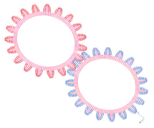
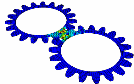
Fig 1: Global view of the mesh.
The finite elements used to model this gear are the thick SHELL16 type elements and the quadratic BRICK20 elements.
A quadratic solid mesh is used to take into account the teeth’s curvature. The external BRICK20 elements are then converted to solid SHELL16 shells using pre-processing. The interface types 16 and 17, manage contact between the quadratic surfaces of the SHELL16 elements.
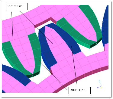
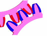
Fig 2: View of the teeth.
Interface types 16 and 17 use the Lagrange multipliers. Type 16 interface is built with a slave node group impacting a quadratic master surface. Type 17 interface is built with two quadratic surfaces.
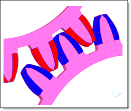
Fig 3: Contact modeling between quadratic surfaces (type 16/17 interfaces).
To apply constant acceleration, start at time, t, with a constant initial rotation phase to reduce the initial value effects. Then, an imposed velocity is applied to the gears to manage a rotational acceleration of 0.002 rad/ms2.
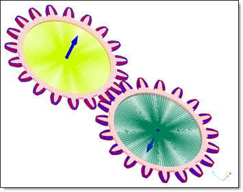
Fig 4: Initial velocities on the temporary rigid bodies’ master nodes.
To apply the initial rotational velocity to the gears, two rigid bodies are created, as shown in Fig 4. Then both the rigid bodies are set to OFF to ensure a realistic deformation of parts after the first loading phase.
The out-of-plane rotation of the rigid bodies is set free. A YZ symmetry plan is used to stabilize the model.
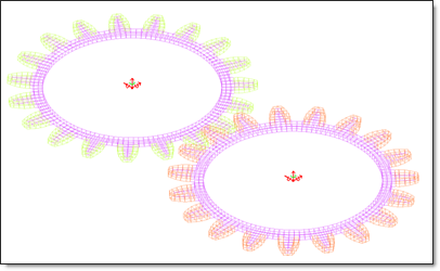
Fig 5: Free out-of-plane rotation of rigid bodies.
Number of options:
Options |
Quantity |
BCS |
3 |
BRIC20 |
950 |
FUNCT |
1 |
GRBRIC |
2 |
GRNOD |
20 |
IMPVEL |
1 |
INIVEL |
2 |
INTER |
1 |
MAT |
1 |
NODE |
10757 |
PART |
3 |
PROP |
3 |
RBODY |
4 |
SENSOR |
1 |
SHEL16 |
380 |
TH |
4 |
Minimum time step: 0.4E-03 ms
Figure 6 shows the application of velocities on the gears.
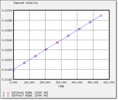
Fig 6: Imposed rotational velocity curves.
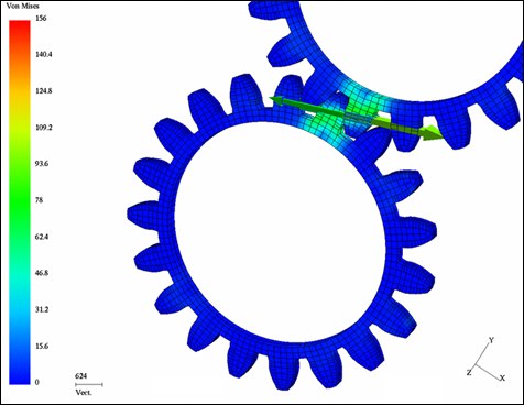
Fig 7: Contact force obtained with type 16 interface.
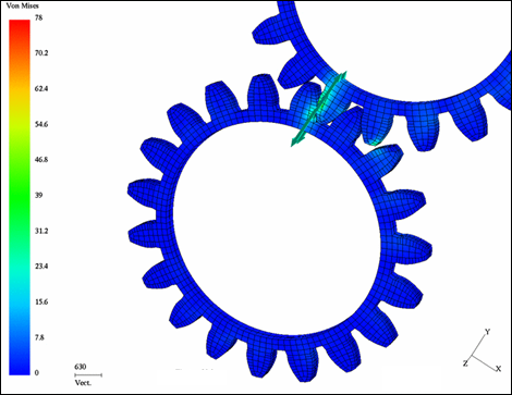
Fig 8: Contact force obtained with type 17 interface.
Figures 7 and 8 compare the contact forces obtained for two different models; one using the interface type 16 and the other using the type 17 interface. The comparison shows that some numerical problems may appear when using the interface type 17, due to the complexity of the algorithms; especially when two surfaces with nonlinear curvatures are used.
On the other hand, interface type 16 obtains an overall physical response.
The type 16 interface provides overall satisfactory results for this kind of application, where the contact surfaces are complex and there is no gap.