HyperWorks Solvers

/MAT/LAW59 (CONNECT)

/MAT/LAW59 (CONNECT)

Previous topic Next topic Expand/collapse all hidden text  

/MAT/LAW59 (CONNECT)

Previous topic Next topic JavaScript is required for expanding text JavaScript is required for the print function  

Block Format Keyword

/MAT/LAW59 - Connection Material

Description

This law describes the Connection material, which can be used to model spotweld, welding line, glue, or adhesive layers in laminate composite material. Elastic and elastoplastic behavior in normal and shear directions can be defined. The curves that represent plastic behavior can be specified for different strain rates. This material is applicable only to solid hexahedron elements (/BRICK) and the material time-step does not depend on element height.

Format

(1)

(2)

(3)

(4)

(5)

(6)

(7)

(8)

(9)

(10)

/MAT/LAW59/mat_ID/unit_ID or /MAT/CONNECT/mat_ID/unit_ID

mat_title


E

G

Imass

Icomp

Ecomp


Nb_fct

Fsmooth

Fcut


Nb_funct lines

(1)

(2)

(3)

(4)

(5)

(6)

(7)

(8)

(9)

(10)

Y_fct_IDN

Y_fct_IDT

SRref

Fscaleyld


hmtoggle_plus1Flag Definition

Field

Contents

SI Unit Example

mat_ID

Material identifier

(Integer, maximum 10 digits)


unit_ID

Optional unit identifier

(Integer, maximum 10 digits)


mat_title

Material title

(Character, maximum 100 characters)


Density

(Real)

symbol_kg

E

Young’s modulus in the normal direction per unit length

(Real)

kg_m2s2

G

Shear modulus in the tangential direction per unit length

(Real)

kg_m2s2

Imass

Mass calculation flag

Default = 0  (Integer)

= 0: Element mass is calculated using density and volume

= 1: Element mass is calculated using density and (means of upper and lower) area


Icomp

Symmetric elasto-plastic behavior in compression

= 0: symmetric elasto-plastic behavior in tension and compression.

= 1: elasto-plastic behavior defined by input yield function in tension only.


Ecomp

Compression modulus

Default = E

kg_m2s2

Nb_fct

Number of input functions: true stress vs plastic elongation (normal or tangential)

(Integer)

= 0: material is linear elastic


Fsmooth

Strain rate filtering flag

Default = 0  (Integer)

= 0: no strain rate filtering

= 1: strain rate filtering


Fcut

Cutoff frequency for the strain rate filtering

Default = 1030  (Real)

symbol_Hz

Y_fct_IDN

True plastic stress vs. elongation in normal direction defined for the reference strain rate

(Integer)


Y_fct_IDT

True plastic stress vs. elongation in tangential direction defined for the reference strain rate

(Integer)


SRref

Strain rate values for which the set of functions are defined

Default = 0.0  (Real)

fail_johnson

Fscaleyld

Scale factor for the plastic stress

Default = 1.0  (Real)

hmtoggle_plus1Example (Spotweld)

#RADIOSS STARTER

/UNIT/1

unit for mat

                 Mg                  mm                   s

#---1----|----2----|----3----|----4----|----5----|----6----|----7----|----8----|----9----|---10----|

#-  2. MATERIALS:

#---1----|----2----|----3----|----4----|----5----|----6----|----7----|----8----|----9----|---10----|

/MAT/LAW59/1/1

spotweld

#              RHO_I

              7.9E-9

#                  E                   G     Imass     Icomp              Ecomp

               21000               21000         0         0                  0

#   NB_fct   Fsmooth                Fcut

         1         1                   0

# Yfct_IDN  Yfct_IDT              SR_ref          Fscale_yld

         1         2                   0                   0

/FAIL/CONNECT/1

#          EPS_MAX_N               EXP_N             ALPHA_N R_fct_IDN     Ifail  Ifail_so      ISYM

                   1                   0                   0         0         0         1         0

#          EPS_MAX_T               EXP_T             ALPHA_T R_fct_IDT

                 1.8                   0                   0         0

#              EIMAX               ENMAX               ETMAX                  Nn                  Nt

                   0                   0                   0                   0                   0

#               Tmax               Nsoft

                   0                   0

#---1----|----2----|----3----|----4----|----5----|----6----|----7----|----8----|----9----|---10----|

#-  3. FUNCTIONS:

#---1----|----2----|----3----|----4----|----5----|----6----|----7----|----8----|----9----|---10----|

/FUNCT/1

New_function

#                  X                   Y

                   0                 250

                   1                 350

#---1----|----2----|----3----|----4----|----5----|----6----|----7----|----8----|----9----|---10----|

/FUNCT/2

New_function

#                  X                   Y

                   0                 350

                   1                 350

#---1----|----2----|----3----|----4----|----5----|----6----|----7----|----8----|----9----|---10----|

#ENDDATA

/END

#---1----|----2----|----3----|----4----|----5----|----6----|----7----|----8----|----9----|---10----|

hmtoggle_plus1Comments
1.This law is compatible with 8-noded hexadedron elements (/BRICK) only. The orientation of the element normal direction with respect to the element faces is important, and is defined as follows:

prop_connect_10

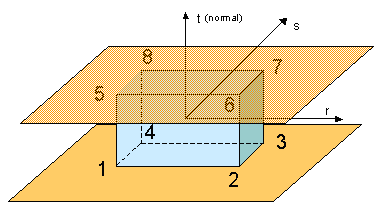
The element local coordinate system is constructed in the mid-plane section between the bottom (1-2-3-4) and top (5-6-7-8) faces.

law59_13_210

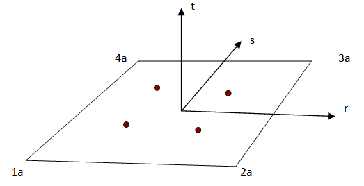
The element has four Gauss integration points placed in the mid-plane section defined by points 1a, 2a, 3a, and 4a. These four points (1a, 2a, 3a, and 4a) lie midway between the bottom and top face nodes, and the orientation of the local coordinate axes (r-s-t) is the same as that of shell elements and t-axis is assume to be directed from bottom face to top face.

2.The stiffness modulus and stresses are defined per elongation in order to be independent from the initial height (from node 1 to 5, in the figure above) of the solid element. For example, E=210000 MPa/mm means that the normal stress increases by 210000 MPa for each 1 mm of elongation until the yield stress limit specified by the yield stress curve is reached.
3.The complete element elongation can be subdivided into an elastic portion (before yield stress is reached) and a portion of the plastic elongation. Plastic elongation is calculated as:

normal_elongation_plastic=total_normal_elongation-true_normal_stress/E

shear_elongation_plastic=total_normal_elongation-true_shear_stress/G

The plastic elongation is accounted for when the normal and tangent yield stress curves are specified. These are usually non-decreasing functions, which represent true stress as a function of the plastic elongation either in normal or in shear direction. The first abscissa value of the function should be “0” and the first ordinate value is the yield stress. The functions may have a stress decrease portion to model material damage.

4.If Icomp =0, the material behavior is elasto plastic in both tension and compression, the compression modulus is given by Ecomp (which by default is equal to E).

If Icomp =1, the material is nonlinear elasto plastic in tension and linear in compression. The compression modulus is given by Ecomp. The normal and shear degrees of freedom are uncoupled and the shear behavior is always symmetrical.

5.The height of the solid element can be equal to zero.
6.All nodes of the solid elements must be connected to other shells or solid elements, slave nodes of rigid body (/RBODY) or slave nodes of tied interface (/INTER/TYPE2).
7.When all nodes of the solid element become free, the element is deleted.
8.The rupture criteria for this material are defined by /FAIL/CONNECT.
9.The material uses special animation and time history output:

USR1 - internal energy

USR2 - internal energy/max value of internal energy described in /FAIL/CONNECT.

USR3 - normal elongation/max value of normal elongation described in /FAIL/CONNECT.

USR4 - normal shear elongation/max value of shear elongation described in /FAIL/CONNECT.

See Also:

Material Compatibility

Law Compatibility with Failure Model

/MAT/LAW59 in Theory Manual

Example 48 - Solid Spotweld