Field
|
Contents
|
dsize_ID
|
Free-size design variable identifier.
(Integer > 0)
|
title
|
Title.
(Character, maximum 100 characters)
|
grpart_ID
|
Part group identifier defining the design space.
(Integer > 0)
|
THICK
|
Indicates if minimum and possibly maximum thickness values need to be defined.
(Integer > 0)
= 0: No
= 1: Yes
|
T0
|
Minimum thickness.
(Real > 0.0 or blank)
|
T1
|
Maximum thickness.
(Real > 0.0 or blank)
|
STRESS
|
Indicates if von Mises stress constraint needs to be defined.
(Integer)
= 0: No
= 1: Yes
|
MAXSTRS
|
Upper bound constraint on von Mises stress.
No default (Real > 0.0)
|
MEMBSIZ
|
Active member size control flag.
(Integer > 0)
= 0: No
= 1: Yes
|
MINDIM
|
Minimum diameter of members formed is specified. This field can be used to eliminate small members. It also eliminates checkerboard results.
Default = No minimum member size control (Real > 0.0)
|
PATRN
|
Active pattern grouping flag.
(Integer)
= 0: No
= 1: Yes
|
TYP
|
Pattern grouping type requested.
Default = No pattern grouping (Integer)
= 1: 1-plane symmetry
= 2: 2-plane symmetry
= 3: 3-plane symmetry
= 10: Cyclic
= 11: Cyclic with symmetry
|
AID
|
Variable pattern grouping anchor node identifier.
(Integer > 0 or blank)
If blank, the XA, YA, and ZA fields should not be blank.
|
XA, YA, ZA
|
Coordinates of the pattern grouping anchor point.
(Real or blank)
If blank, AID should not be blank.
|
FID
|
Node identifier that defines the direction of the first vector for variable pattern grouping.
(Integer > 0 or blank)
If blank, the XF, YF, and ZF fields should not be blank.
|
XF, YF, ZF
|
Components of the first vector that defines pattern grouping.
(Real or blank)
If blank, FID should not be blank.
|
UCYC
|
Number of cyclical repetitions for cyclical symmetry. This field defines the number of radial "wedges" for cyclical symmetry. The angle of each wedge is computed as: 360.0/UCYC.
Default = blank (Integer > 0 or blank)
|
SID
|
Node identifier of the second point for pattern grouping definition.
(Integer or blank)
If blank, the XS, YS, and ZS should not be blank.
|
XS, YS, ZS
|
Coordinates of the second point for pattern grouping definition.
(Real or blank)
If blank, SID should not be blank.
|
PATREP
|
Indicates if pattern repetition is defined and repetition type.
(Integer)
= 0: no pattern repetition
= 1: pattern repetition is defined and this design variable is master
= 2: pattern repetition is defined and this design variable is slave
|
masterID
|
Master /DSIZE identifier for pattern definition.
(Integer > 0)
This field is required only for PATREP =2.
|
SX, SY, SZ
|
Scale factors for pattern repetition in the X, Y, and Z directions, respectively.
Default = 1.0 (Real > 0.0)
|
ptrepCID
|
Skew identifier used as the pattern repetition coordinate system.
Default = 0 (Integer > 0)
|
CAID
|
Node identifier of an anchor point for the definition of a pattern repetition coordinate system.
(Integer > 0 or blank)
If blank, the XCA, YCA, and ZCA fields should not be blank.
|
XCA, YCA, ZCA
|
Coordinates of an anchor point for the definition of a pattern repetition coordinate system.
(Real or blank)
If blank, CAID should not be blank.
|
CFID
|
Node identifier of the first point for the definition of a pattern repetition coordinate system.
(Integer > 0 or blank)
If blank, the XCF, YCF, and ZCF fields should not be blank.
|
XCF, YCF, ZCF
|
Coordinates of the first point for the definition of a pattern repetition coordinate system.
(Real or blank)
If blank, CFID should not be blank.
|
CSID
|
Node identifier of a second point for the definition of a pattern repetition coordinate system.
(Integer > 0 or blank)
If blank, the XCS, YCS, and ZCS fields should not be blank.
|
XCS, YCS, ZCS
|
Coordinates of a second point for the definition of a pattern repetition coordinate system.
(Real or blank)
If blank, CSID should not be blank.
|
CTID
|
Node identifier of a third point for the definition of a pattern repetition coordinate system.
(Integer > 0 or blank)
If blank, the XCT, YCT, and ZCT fields should not be blank.
|
XCT, YCT, ZCT
|
Coordinates of a third point for the definition of a pattern repetition coordinate system.
(Real or blank)
If blank, CTID should not be blank.
|
NGROUP
|
Number of element groups used in zone based free-sizing optimization.
Default = 0 (Integer > 0)
|
ETYPi
|
Type of followed element group.
(Integer > 0), i=1, …, NGROUP
= 201: /GRSHEL
= 202: /GRSH3N
|
EGRPi
|
Element group numbers used in zone based free-sizing optimization.
(Integer > 0), i=1, …,NGROUP
|
COMP
|
Composite manufacturing constraints applied are indicated. Information about manufacturing constraints is to follow. The value of COMP is equal to the total number of composite manufacturing definitions that follow.
|
CTYP
|
Composite manufacturing type definition flag.
(Integer)
= 1: laminate thickness constraints are applied. Multiple laminate thickness constraints are allowed.
= 2: ply thickness constraints are applied. Multiple ply thickness constraints are allowed.
= 3: ply thickness percentage constraints are applied. Multiple ply thickness percentage constraints are allowed.
= 4: manufacturable ply thickness constraints are applied. Multiple manufacturable ply thickness constraints are allowed.
= 5: a balance constraint is applied. Multiple balance constraints are allowed.
= 6: a constant thickness constraint is applied. Multiple constant thickness constraints are allowed.
= 7: ply drop-off constraints are applied. Multiple ply drop-off constraints are allowed.
|
LTMIN
|
Minimum laminate thickness for the laminate thickness constraint (CTYP = 1).
(Real or blank)
|
LTMAX
|
Maximum laminate thickness for the laminate thickness constraint (CTYP = 1).
(Real or blank)
|
GRSH3N
|
3-node shell group identifier
(Integer > 0)
|
GRSH4N
|
4-node shell group identifier
(Integer > 0)
|
LTEXC
|
Indicates that certain plies are excluded from the laminate thickness constraint (CTYP = 1). Support options are:
(Integer)
= 0: Plies are not excluded.
= 1: The core is excluded (default).
= 2: Plies defined in the constant thickness constraint (CTYP = 6) are excluded.
= 3: 1 and 2 are considered.
|
PTANGLE
|
Ply orientation in degrees to which the ply thickness constraint (CTYP = 2) is applied.
(Real)
|
PTMIN
|
Minimum thickness for the ply thickness constraint (CTYP = 2).
(Real or blank)
|
PTMAX
|
Maximum thickness for the ply thickness constraint (CTYP = 2).
(Real or blank)
|
PTEXC
|
Indicates that certain plies are excluded from the ply thickness constraint (CTYP = 2). Supported options are:
(Integer)
= 0: Plies are not excluded.
= 1: The core is excluded (default).
= 2: Plies defined in the constant thickness constraint (CTYP = 6) are excluded.
= 3: 1 and 2 are considered.
|
PPANGLE
|
Ply orientation in degrees to which the ply thickness percentage constraint is applied (CTYP = 3).
(Real)
|
PPMIN
|
Minimum percentage thickness for the ply thickness percentage constraint (CTYP = 3).
(Real or blank)
|
PPMAX
|
Maximum percentage thickness for the ply thickness percentage constraint (CTYP = 3).
(Real or blank)
|
PPEXC
|
Indicates that certain plies are excluded from the ply thickness percentage constraint (CTYP = 3). Supported options are:
(Integer)
= 0: Plies are not excluded.
= 1: The core is excluded (default).
= 2: Plies defined in the constant thickness constraint (CTYP = 6) are excluded.
= 3: 1 and 2 are considered
|
PMANGLE
|
Ply orientation in degrees to which the manufacturable ply thickness constraint is applied (CTYP = 4).
(Real)
|
PMMAN
|
Manufacturable ply thickness.
Default = blank (Real > 0.0)
|
PMEXC
|
Indicates that certain plies are excluded from the manufacturable ply thickness constraint (CTYP = 4). Supported options are:
(Integer)
= 0: Plies are not excluded.
= 1: The core is excluded (default).
= 2: Plies defined in the constant thickness constraint (CTYP = 6) are excluded.
= 3: 1 and 2 are considered.
|
BANGLE1
|
First ply orientation in degrees to which the balance constraint is applied (CTYP = 5).
(Real)
|
BANGLE2
|
Second ply orientation in degrees to which the balance constraint is applied (CTYP = 5).
(Real)
|
CANGLE
|
Ply orientation in degrees to which the constant thickness constraint is applied (CTYP = 6).
(Real)
|
CTHICK
|
Constant ply thickness for the constant thickness constraint (CTYP = 6).
(Real)
|
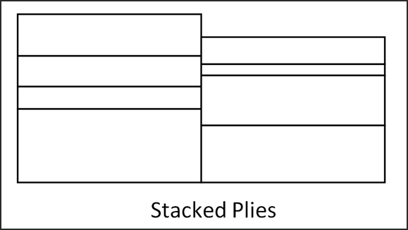
PDANGLE
|
Ply orientation in degrees to which the ply drop-off constraint is applied (CTYP = 7).
(Real)
|
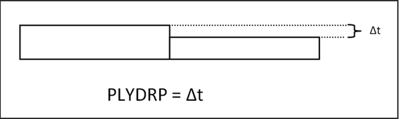
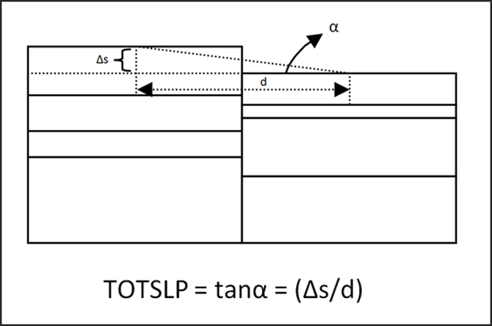
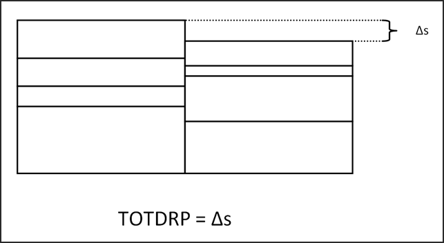
PDTYP
|
Drop-off constraint type:
(Integer)
= 0: PLYSLP (default)
= 1: PLYDRP
= 2: TOTSLP
= 3: TOTDRP
(Comment 2)
|
PDMAX
|
Maximum allowed drop-off for the ply drop-off constraint (CTYP = 7).
(Real)
|
PDEXC
|
Indicates that certain plies are excluded from the ply drop-off constraint (CTYP = 7). Supported options are:
(Integer)
= 0: Plies are not excluded.
= 1: The core is excluded (default).
= 2: Plies defined in the constant thickness constraint (CTYP = 6) are excluded.
= 3: 1 and 2 are considered.
|