HyperWorks Solvers

/DTPG

/DTPG

Previous topic Next topic Expand/collapse all hidden text  

/DTPG

Previous topic Next topic JavaScript is required for expanding text JavaScript is required for the print function  

Optimization Keyword

/DTPGDesign Variable for Topography Optimization

Description

Defines parameters for the generation of topography design variables.

Format

(1)

(2)

(3)

(4)

(5)

(6)

(7)

(8)

(9)

(10)

/DTPG/dtpg_ID

title

TYPE

grpart_ID

dvg_ID

PATRN

PATRN2

PATREP

BOUNDS


If PATREP =0 or 1, read bead definition:

(1)

(2)

(3)

(4)

(5)

(6)

(7)

(8)

(9)

(10)

MW

ANG

BF

HGT

SKIP


norm

XD

YD

ZD


If PATRN =1, read pattern grouping constraint definition:

(1)

(2)

(3)

(4)

(5)

(6)

(7)

(8)

(9)

(10)

TYP

AID

XA

YA

ZA


FID

XF

YF

ZF


If PATRN2 =1, read pattern grouping constraint definition:

(1)

(2)

(3)

(4)

(5)

(6)

(7)

(8)

(9)

(10)

UCYC

SID

XS

YS

ZS


If BOUNDS =1, read limits and initial value definition for grid movement:

(1)

(2)

(3)

(4)

(5)

(6)

(7)

(8)

(9)

(10)

LB

UB

INIT


If PATREP =1, read MASTER definitions for pattern repetition constraint:

(1)

(2)

(3)

(4)

(5)

(6)

(7)

(8)

(9)

(10)

ptrepCID


CAID

XCA

YCA

ZCA


CFID

XCF

YCF

ZCF


CSID

XCS

YCS

ZCS


CTID

XCT

YCT

ZCT


If PATREP =2, read SLAVE definitions for pattern repetition constraint:

(1)

(2)

(3)

(4)

(5)

(6)

(7)

(8)

(9)

(10)

masterID

SX

SY

SZ


ptrepCID


CAID

XCA

YCA

ZCA


CFID

XCF

YCF

ZCF


CSID

XCS

YCS

ZCS


CTID

XCT

YCT

ZCT


hmtoggle_plus1Flag Definition

Field

Contents

dtpg_ID

Topography design variable identifier.

(Integer > 0)

title

Title.

(Character, maximum 100 characters)

TYPE

Indicates whether topography design variable is defined by PART group or /DVGRID.

(Integer)

= 1: topography design variable is defined by option grpart_ID

= 2: topography design variable is defined by option dvg_ID

grpart_ID

Part group identifier defining the design space, it must be defined explicitly only when TYPE =1.

(Integer > 0)

dvg_ID

/DVGRID identifier defining the design variable number of a set of DVGRIDs, it must be defined explicitly only when TYPE =2.

(Integer > 0)

MW

Bead minimum width. This parameter controls the width of the beads in the model [recommended value between 1.5 and 2.5 times the average element width]. See comment 1.

(Real > 0.0)

ANG

Draw angle in degrees. This parameter controls the angle of the sides of the beads (recommended value between 60 and 75 degrees). See comment 1.

(1.0 < Real < 89.0)

BF

Active buffer zone flag. This parameter will establish a buffer zone between elements in the design domain and elements outside the design domain. See comment 2.

Default = 1 (Integer)

= 0: No, not active

= 1: Yes, active

HGT

Draw height. This parameter sets the maximum height of the beads to be drawn. This field is only valid if TYPE =1.

(Real > 0.0)

norm

Indicates if shape variable is created in the normal directions of the elements. (only valid when TYPE =1)

Default = 1 (Integer or blank)

= 0: No

= 1: Yes

XD, YD, ZD

The X, Y and Z component of a vector in the global coordinate system. If all these three values are Real, the shape variable will be created in the direction specified by the xyz vector defined by the three fields. (only valid when TYPE =1)

(Real or blank)

SKIP

Skip boundary flag. This parameter tells the solver to leave certain nodes out of the design domain. This field is only valid if TYPE =1.

Default = 4 (Integer)

= 1: all nodes attached to elements in part group grpart_ID will be a part of the shape variables.

= 2: any nodes which have /BCS declarations are omitted from the design domain.

= 3: any nodes which have force defined, like /CLOAD or /IMPDISP declarations are omitted from the design domain.

= 4: nodes with either boundary condition or force defined are omitted from the design domain, an option for 2 and 3 combination.

PATRN

Active pattern grouping flag.

(Integer)

= 0: No

= 1: Yes

TYP

Variable grouping pattern type. Required if any symmetry or variable pattern grouping is desired. If zero or blank, anchor node, first vector, and second vector definitions are ignored. If less than 20, second vector definition is ignored. See comment 4.

Default = 0 (Integer > 0)

AID

Variable pattern grouping anchor node identifier. See comment 3.

(Integer > 0 or blank)

If blank, the XA, YA, and ZA fields must not be blank.

XA, YA, ZA

Coordinates of the pattern grouping anchor point. See comment 3.

(Real or blank)

If blank, AID must not be blank.

FID

Node identifier that defines the direction of the first vector for variable pattern grouping. See comment 3.

(Integer > 0 or blank)

If blank, the XF, YF, and ZF fields must not be blank.

XF, YF, ZF

Components of the first vector defining pattern grouping. See comment 3.

(Real or blank)

If blank, FID must not be blank.

PATRN2

Active variable pattern grouping flag.

(Integer)

= 0: No

= 1: Yes

UCYC

Number of cyclical repetitions for cyclical symmetry. This field defines the number of radial "wedges" for cyclical symmetry. The angle of each wedge is computed as 360.0/UCYC. See comment 4.

Default = blank (Integer > 0 or blank)

SID

Node identifier of the second point for pattern grouping definition. See comment 3.

(Integer or blank)

If blank, the XS, YS, and ZS fields must not be blank.

XS, YS, ZS

Coordinates of second point for pattern grouping. See comment 3.

(Real or blank)

If blank, SID must not be blank.

BOUNDS

Indicates that information on upper and lower limits and the initial value for grid movement are defined.

(Integer)

= 0: No

= 1: Yes

LB

Lower bound on variables controlling grid movement. This sets the lower bound on grid movement equal to LB*HGT.

Default = 0.0 (Real < UB)

UB

Upper bound on variables controlling grid movement. This sets the upper bound on grid movement equal to UB*HGT.

Default = 1.0 (Real > LB)

INIT

The initial value of the variables controlling grid movement. This sets the initial value on grid movement equal to INIT*HGT.

(LB < Real < UB)

PATREP

Pattern repetition definition flag.

(Integer)

= 0: no pattern repetition

= 1: pattern repetition is defined, and this design variable is master.

= 2: pattern repetition is defined, and this design variable is slave.

masterID

Master /DTPG identifier for pattern definition.

(Integer > 0) Only needed for PATREP =2

SX, SY, SZ

Scale factors for pattern repetition in X, Y, and Z directions respectively.

Default = 1.0 (Real > 0.0)

ptrepCID

Skew identifier used as the pattern repetition coordinate system. See comment 6.

Default = 0 (Integer > 0)

CAID

Node identifier of an anchor point for the definition of a pattern repetition coordinate system. See comment 6.

(Integer > 0 or blank)

If blank, the XCA, YCA, and ZCA fields must not be blank.

XCA, YCA, ZCA

Coordinates of the anchor point for the definition of a pattern repetition coordinate system. See comment 6.

(Real or blank)

If blank, CAID must not be blank.

CFID

Node identifier of the first point for the definition of a pattern repetition coordinate system. See comment 6.

(Integer > 0 or blank)

If blank, the XCF, YCF, and ZCF fields must not be blank.

XCF, YCF, ZCF

Coordinates of the first point for the definition of a pattern repetition coordinate system. See comment 6.

(Real or blank)

If blank, CFID must not be blank.

CSID

Node identifier of the second point for the definition of a pattern repetition coordinate system. See comment 6.

(Integer > 0 or blank)

If blank, the XCS, YCS, and ZCS fields must not be blank.

XCS, YCS, ZCS

Coordinates of the second point for the definition of a pattern repetition coordinate system. See comment 6.

(Real or blank)

If blank, CSID must not be blank.

CTID

Node identifier of the third point for the definition of a pattern repetition coordinate system. See comment 6.

(Integer > 0 or blank)

If blank, the XCT, YCT, and ZCT fields must not be blank.

XCT, YCT, ZCT

Coordinates of the third point for the definition of a pattern repetition coordinate system. See comment 6.

(Real or blank)

If blank, CTID must not be blank.

hmtoggle_plus1Comments
1.The bead minimum width and draw angles are used to determine the geometry of the shape variables. The figure below shows a cross-section of a single shape variable fully extended normal to the plane of the design elements. The top of the bead is flat across the circular area with a diameter equal to the minimum bead width parameter. The sides of the bead taper down at an angle equal to the draw angle parameter.

beadfig1

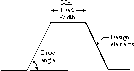
Bead width and draw angle definitions

2.The buffer zone is a parameter that controls how the interfaces between design and non-design elements are treated. If active, OptiStruct will place the shape variables far enough away from the non-design elements so that the proper bead widths and draw angles are maintained. If inactive, the boundary between the beads and non-design elements will have an abrupt transition. Any nodes that were skipped due to the boundary skip parameter will also have a buffer zone created around them.

beadfig2

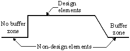
Transitions between design and non-design elements with and without buffer zone

3.Symmetry of topography optimization can be enforced across one, two, or three planes. Defining symmetry planes for symmetric model and loading conditions is recommended because automatic variable generation may not be symmetric if it is not enforced. A symmetric mesh is not necessary, OptiStruct will create variables that are very close to identical across the plane(s) of symmetry. If the mesh is larger on one side of the plane(s) of symmetry than the other, OptiStruct will reflect variables created on the ‘positive’ side of the plane(s) of symmetry to the other side(s) but will not create variables on the ‘negative’ side(s) of the plane(s) of symmetry that do not overlap with the positive side. The positive side of the plane(s) of symmetry is the one in which the first vector, second vector, and cross product thereof are pointing toward.
4.Variable pattern grouping may be defined for a DTPG card. OptiStruct will generate shape variables based on the type of pattern selected in field “TYP”. For variable grouping pattern types 1 through 14, only the first vector and anchor node need to be defined. For variable pattern grouping types 20 or higher, the first and second vectors need to be defined as well as the anchor node. If a grid is used to define the first vector, the normal vector will begin at the anchor point and extend towards the given grid (see below). Grids or xyz data may be used to define the first vector, second vector, or anchor point and can be a mixture (that is the anchor point may be determined by a grid and the first vector determined by xyz data or vice-versa).

One very useful feature for topography optimization in OptiStruct is the automatic generation of shape variables in simple patterns. In many cases, due to manufacturing constraints or the risk of elements being collapsed upon them during shape optimization, it is required to create shape variables in patterns that conform to the desired shape of the part. In basic topography optimization (TYP = 0), OptiStruct creates shape variables that are circular. OptiStruct contains a library of different shape variable patterns which can be accessed using the TYP parameter on the DTPG card.

beadfig3

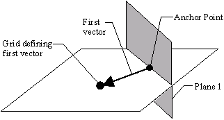
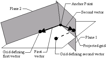
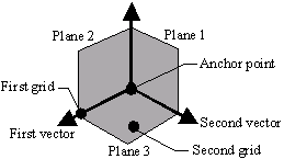
Defining the first vector using a grid point

The second vector is calculated by taking the grid point (SID) or vector defined in fields “XS, YS, and ZS” and projecting it onto plane 1. If a grid point was used to define the second vector, the second vector is a vector running from the anchor node to the projected grid point. If a vector was used to define the second vector, the base of the projected vector is placed at the anchor point. The second vector is normal to plane 2 (see below).

beadfig4

Plane 3 is determined to be normal to both plane 1 and plane 2 (see below).

beadfig5

5.For a list of patterns supported by OptiStruct, refer to Pattern Grouping Options.
6.Pattern repetition allows similar regions of the design domain to be linked together so as to produce similar topographical layouts. This is facilitated through the definition of "Master" and "Slave" regions. A DTPG card may only contain one MASTER or SLAVE flag. Bead parameters will not be exported for any DTPG cards containing the SLAVE flag. For both "Master" and "Slave" regions, a pattern repetition coordinate system is required and is described following the COORD flag. In order to facilitate reflection, the coordinate system may be a left-handed or right-handed Cartesian system. The coordinate system may be defined in one of two ways, listed here in order of precedence:
Three points are defined and these are utilized as follows to define the coordinate system (this is the only way to define a left-handed system):
-A vector from the anchor point to the first point defines the x-axis
-The second point lies on the x-y plane, indicating the positive sense of the y-axis
-The third point indicates the positive sense of the z-axis
A rectangular coordinate system and an anchor point are defined. If only an anchor point is defined, it is assumed that the basic coordinate system is to be used.

Multiple "Slaves" may reference the same "Master."

Scale factors may be defined for "Slave" regions, allowing the "Master" layout to be adjusted.

For a more detailed description, refer to the Pattern Repetition page contained within the User's Guide section Manufacturability for Topography Optimization.

See Also:

Design Optimization