Pattern repetition is a technique where different structural components can be linked together so as to produce similar topological layouts.
To achieve this, a master DTPL card needs to be defined, followed by any number of slave DTPL cards which reference the master. The master and slave components are related to each other through local coordinate systems, which are required, and through scaling factors, which are optional.
Other manufacturing constraints, such as minimum or maximum member size, draw direction constraints or extrusion constraints, can be applied to the master DTPL card. These constraints will then automatically be applied to the slave DTPL card(s) as described in the sections below.
The following procedure should be followed to set up pattern repetition:
| 1. | Create a master DTPL card. |
| 2. | Apply other manufacturing constraints as needed. |
| 3. | Define the local coordinate system associated to the master DTPL card. |
| 4. | Create a slave DTPL card. |
| 5. | Define the local coordinate systems associated to the slave DTPL card. |
| 6. | Apply scaling factors as needed. |
| 7. | Repeat steps 4-6 for any number of slave DTPL cards. |
Local Coordinates Systems
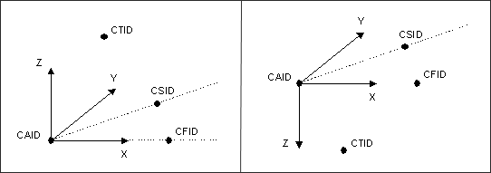
Local coordinates systems are generated by providing four points. These points can be defined either by entering explicit coordinates or by referencing existing grids, as follows:
| 1. | CAID defines the anchor point for the local coordinates system. |
| 2. | CFID defines the direction of the X-axis. |
| 3. | CSID defines the XY plane and indicates the positive sense of the Y-axis. |
| 4. | CTID indicates the positive sense of the Z-axis. |
The definition of the fourth point allows for both right-handed and left-handed coordinate systems, which facilitates the creation of reflection patterns.
| Right-handed coordinates system | Left-handed coordinates system |
Alternatively, local coordinate systems can be defined by referencing an existing rectangular coordinate system in the CID field, and by defining an anchor point in the CAID field.
Note that if the fields defining CFID, CSID, CTID, and CID are left blank, the global coordinates system is used by default. The anchor point CAID, however, is always required.
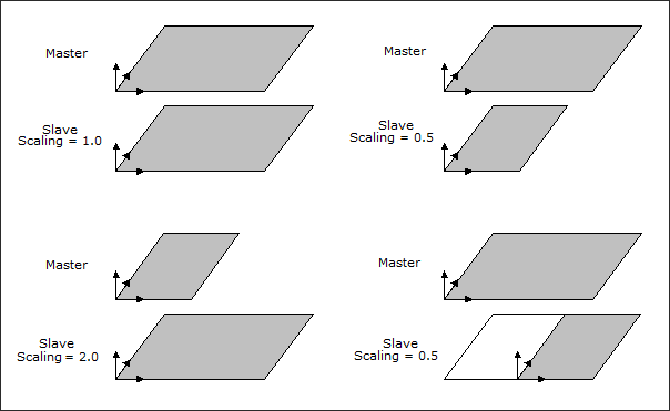
Scaling Factors
Scaling factors in the X, Y, and Z directions can be defined for each slave DTPL card. These factors are always related to the local coordinate system. By playing with the local coordinate systems and the scaling factors, a wide range of effects can be obtained as illustrated in the figure below.
Pattern Repetition with Draw Direction Constraints
Draw direction constraints can be applied simultaneously with pattern repetition. To achieve this, simply define the draw direction for the master DTPL card, and the draw direction for the slave(s) will automatically be generated based on the local coordinate system.
Even if some components are not naturally identical, the optimized design for each component will still satisfy the draw direction constraints. In particular, if different components contain different obstacles, the combination of all obstacles will always be considered.
Pattern Repetition with Extrusion Constraints
Extrusion constraints can also be used in conjunction with pattern repetition. This allows for creating parts which have identical cross-sections. The components do not need to be identical in a three-dimensional sense; each part can have its own extrusion path.
If the components have different extrusion paths, these paths have to be defined explicitly on each DTPL card. However, if the components have identical extrusion paths, the paths for the slave(s) will automatically be computed based on the master's extrusion path.
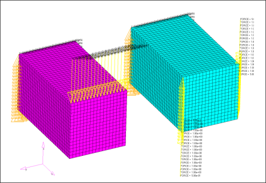
This example shows how pattern repetition may be used to generate the same topology in different parts. The first figure shows two similar blocks loaded in two different ways. The optimization problem is to minimize the compliance with 30 percent volume fraction.
If pattern repetition is not used, the optimized topologies are different, as shown in the figures below:
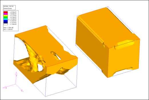
Same view as in the first figure.
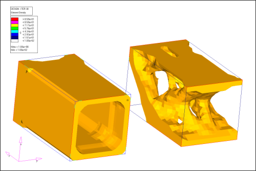
Viewed from behind showing that the turquoise block is hollowed out.
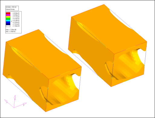
Using pattern repetition, both of the loads on the master (the left hand block in first figure) and the loads on the slave are taken into account, and the optimized topology is repeated for both blocks, as shown below:
|
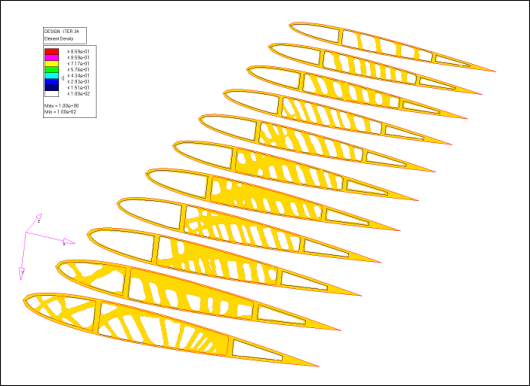
This example shows a simplified wing model.
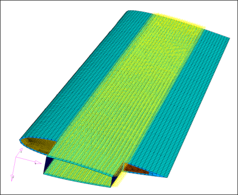
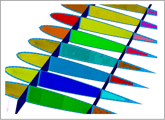
The internal wing structure consists of 2 spars and 11 ribs. In this example, each rib is subdivided into three sections; the nose section, the center section and the tail section, and each of these sections is chosen as a topology design region.
The optimization problem is to minimize compliance for 30 percent of the design volume fraction. Here you see the optimized topology when each region is independent.
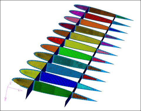
Pattern repetition is used to group all of the noses together, all of the centers together and all of the tails together, resulting in 3 master pattern definitions, each with 10 slave definitions. Notice how different meshes are used for each rib; pattern repetition is mesh independent. Also the wing tapers, so the outboard ribs are shorter and thinner than the inboard ribs, scaling is defined for the slaves so that the pattern fits in the design space.
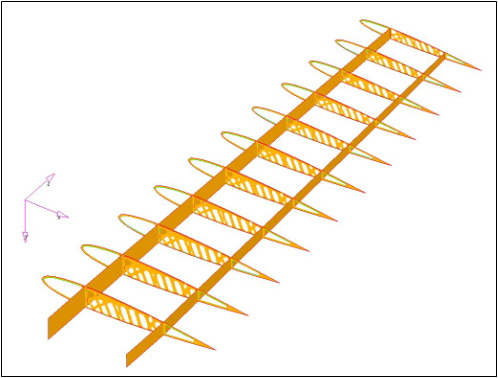
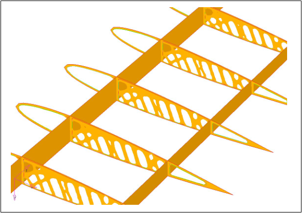
The optimized topology achieved using pattern repetition is shown below, and you can see how the same topological layout is repeated for each rib.
|
See Also:
Multi-Model Optimization


