In some cases, it is desirable to produce a design characterized by a constant cross-section along a given path, particularly for parts manufactured through an extrusion process. By using extrusion manufacturing constraints in topology optimization, constant cross-section designs can be attained for solid models – regardless of the initial mesh, boundary conditions or loads.
Extrusion constraints can also be used for the conceptual design study of structures that do not specifically need to be manufactured using an extrusion procedure. Those requirements can be regarded as specific geometric constraints and can be used for any design that desires such characteristics. For instance, it might be desirable to have ribs going through the entire depth of a solid domain.
As with other manufacturing constraints, extrusion constraints can be applied on a component level, and can be defined in conjunction with minimum member size control using the DTPL card.
Setting up the Problem
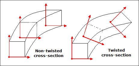
Extrusion constraints can be applied to domains characterized by non-twisted cross-sections (left figure) or twisted cross-sections (right figure) by using the NOTWIST or TWIST parameters respectively in the ETYP field. The structure is non-twisted when the local coordinates systems associated with each cross-section, projected onto a reference plane, remain parallel to each other.
Defining the Extrusion Path
It is necessary to define a ‘discrete’ extrusion path by entering a series of grids in the EPATH1 field. The curve between these grids is then interpolated using parametric splines. The minimum amount of grids depends on the complexity of the extrusion path. Only two grids are required for a linear path, but it is recommended to use at least 5-10 grids for more complex curves.
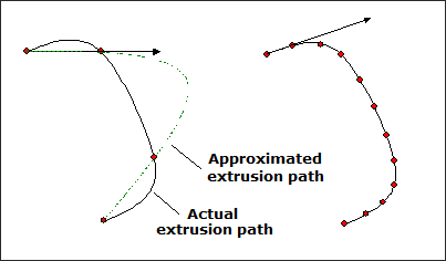
In the example above, four grids are used to define the extrusion path (left figure), where the path computed by OptiStruct is inaccurate. To obtain a more accurate approximation, more grids are included in the extrusion path (right figure).
For twisted cross-sections, a secondary extrusion path needs to be defined in a similar manner through the EPATH2 field.
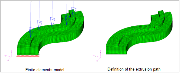
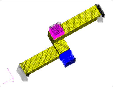
In this example, a curved beam is considered to be a rail over which a vehicle is moving. Both ends of the beam are simply supported. A point load applied over the length of the rail as five independent load cases simulates the movement of the vehicle. The objective is to minimize the sum of the compliances, and the material volume fraction is constrained at 0.3. The rail should be manufactured through extrusion. The 13 grids represented as black dots on the right figure define the extrusion path.
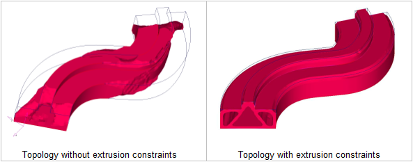
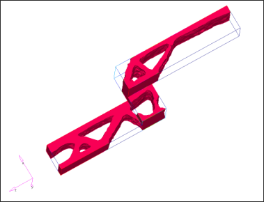
The optimized topologies without and with extrusion constraints are shown below. Reanalyzing the final designs without penalty for intermediate density, the compliances for these two designs are 29.9396 and 37.4377 respectively, which implies a 20% loss in performance due to extrusion constraints. The extruded design represents a clean proposal that requires little refinement. On the other hand, the design obtained without manufacturing constraints may require significant modifications that could cause efficiency loss in performance.
|
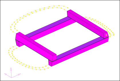
In this example, a "stairs" shaped structure is submitted to two lateral pressure loads defined in two separate subcases. The objective is to minimize the sum of the compliances under both load cases. The extrusion path is defined as a straight line parallel to the global Y-axis. The cross-section of the finite elements model along that path is not constant.
Clearly, this type of structure is not suitable to be manufactured through an extrusion process. However, extrusion constraints can be applied to obtain a manufacturable design characterized by ribs going through the entire depth of the structure. The optimized design gives a good idea of the layout of the resulting stiffening panels.
|
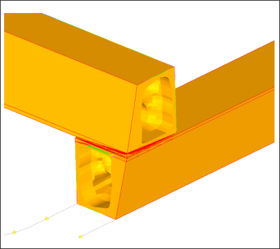
This example illustrates how extrusion constraints can be used to develop common components in different areas of a structure. The extrusion path can be defined through a solid mesh that is not continuous.
|
See Also:
Multi-Model Optimization


