Member size control allows you some control over the member size in the final topology and the resulting degree of simplicity of the final design. This feature may be added one of the two ways described below.
(1)
|
(2)
|
(3)
|
(4)
|
(5)
|
(6)
|
(7)
|
(8)
|
(9)
|
(10)
|
DOPTPRM
|
MINDIM
|
VALUE
|
|
|
|
|
|
|
|
Here, only the preferred minimum diameter (width in 2D) of members may be defined as the VALUE field, following the MINDIM keyword. A global minimum member size is defined in this way.
(1)
|
(2)
|
(3)
|
(4)
|
(5)
|
(6)
|
(7)
|
(8)
|
(9)
|
(10)
|
DTPL
|
ID
|
PTYPE
|
PID1
|
PID2
|
PID3
|
PID4
|
PID5
|
PID6
|
|
|
PID7
|
…
|
…
|
…
|
|
|
|
|
|
|
MEMBSIZ
|
MINDIM
|
MAXDIM
|
MINGAP
|
|
|
|
|
|
Here, both the preferred minimum, MINDIM, and the maximum, MAXDIM, diameter of members may be defined on the MEMBSIZ continuation line. Member size dimensions can be defined differently for each DTPL in this way.
Minimum Member Size Control
Although minimum member size control penalizes the formation of small members, results that contain members significantly under the specified minimum member size can still be obtained. This is because a small member in the structure can be very important to the load transmission and may not be removed by penalization. Minimum member size control functions more as a quality control than a quantity control.
A discrete solution is achieved in two iterative steps. The first step converges to a solution with a large number of semi-dense elements. The second step tries to refine this solution to a solution with fully dense members. Each step consists of a number of iterations. The first step consists of two entire convergence phases - the first run with the initial discreteness values (defined by DISCRETE and DISCRT1D parameters on the DOPTPRM bulk data entry), followed by a run with the discreteness values increased by 1.0. This procedure is implemented in order to achieve a solution with clearly defined members. If this step could not create a solution with clearly defined members, the preferred minimum member size will not be preserved in the second step. In which case, you need to increase the discreteness parameters and/or reduce the convergence tolerance (defined by the OBJTOL parameter on the DOPTPRM bulk data entry) to improve the solution of the first phase. The default discreteness is set to 1.0 for 1D elements, plates and shells, and 2.0 for 3D solids.
In general, once MINDIM is activated, checkerboarding is controlled by the methods applied for this feature, eliminating the need for the CHECKER parameter. In rare circumstances, checkerboards may still be introduced in the second phase described above for 3D solids. If this happens, an additional checkerboard control algorithm can be activated with the MMCHECK parameter. (The CHECKER and MMCHECK parameters are defined using the DOPTPRM bulk data entry).
The use of this card will assure a checkerboard-free solution, although with the undesired side effect of achieving a solution that involves a large number of semi-dense elements, similar to the result of setting CHECKER equal to 1. Therefore, use this card only when it is necessary.
It is recommended that MINDIM be at least 3 times, and no greater than 12 times, the average element size for all elements referenced by that DTPL (or all designable elements when defined on DOPTPRM). The average element size for 2D elements is calculated as the average of the square root of the area of the elements, and for 3D elements, as the average of the cubic root of the volume of the elements.
This recommendation is enforced when combined with other manufacturing constraints, and if the defined MINDIM is less than this value, it will be reset to a default value equal to 3 times the average element size. Similarly, if the defined MINDIM is larger than 12 times the average element size, it will be reset to a value equal to 12 times the average element size. This limit has been set to trim memory requirements that can become too large as a result of having to keep track of a much larger number of elements needed to satisfy the MINDIM constraint. In structures where the mesh is aligned with the draw or extrusion direction, setting MTYP as ALIGN on the MESH continuation line of the DTPL card may circumvent this constraint.
The following examples demonstrate significant improvement in the manufacturability of results through the use of minimum member size control:
Michell-truss Example
MBB-Beam Example
Arch Example
3D Bridge Model Example
Maximum Member Size Control
Maximum member size control penalizes the formation of large members. The control is not directional, meaning that if the thickness of a member is less than MAXDIM in any direction, this constraint is satisfied. This reflects the need to control the rib thickness of casting parts.
MAXDIM must be at least twice MINDIM, and hence the minimum mesh requirement is that MAXDIM has to be at least 6 times the average element size for all elements referenced by that DTPL. This constraint is strongly enforced and an error termination will occur when this criteria is not met. In addition, MAXDIM should be less than half the width of the thinnest part of the design region.
Based on the constraints mentioned above, a fine mesh is required to achieve good results with this manufacturing constraint.
It is to be noted that use of the maximum member size control induces further restriction of the feasible design space and should therefore only be used when it is truly desirable. Also note that this feature is a new research development, and the techniques are still undergoing improvement. An undesired side effect that has been noticed for some examples is that it might result in more intermediate density in the final solution. Therefore, it is recommended that this feature be used sparingly until the technology becomes more robust.
While MAXDIM also enforces a spacing of members of the same dimension, the maximum reachable volume fraction is 0.5. For problems involving constraints on structural responses, this could interfere with constraint satisfaction. It is strongly recommended that the behavior of the design problem be studied without MAXDIM first in order to determine if the use of MAXDIM would be advantageous, and if the target volume allows for it to be applied.
The following examples demonstrate the impact of maximum member size control to the design outcome.
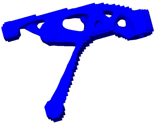
Engine Bracket Design with Draw Direction Constraint
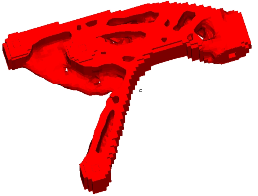
Engine Bracket Design with Draw Direction and Maximum Member Size Constraints
|
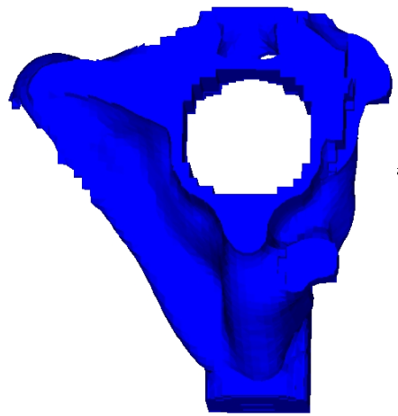
Steering Wheel Bracket Design with Draw Direction Constraint
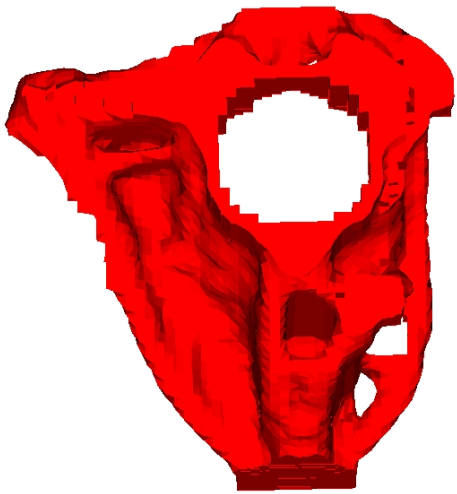
Steering Wheel Bracket Design with Draw Direction and Maximum Member Size Constraints
|
See Also:
Manufacturability for Topology Optimization
Multi-Model Optimization


